
Introduction to PCS Voltage Ride-Through (VRT) Technology
- Author: Overseas Business Division · Technology Center
- Applicable Products: ENJOY EPCS125-AM / EPCS105-AM series Power Conversion Systems (PCS)
I. Overview
Voltage Ride-Through (VRT) is a mandatory compliance requirement for grid-connected power electronic equipment (PCS, PV inverters, wind converters, etc.). It requires that when the grid voltage undergoes transient deviations due to faults or other reasons, the equipment remains connected, actively supports the grid, and recovers according to dispatch instructions—rather than simply "tripping off the moment it sees a low voltage."
As the share of renewable energy installations continues to grow (the EU's combined wind and solar generation exceeded 40% in 2025), the traditional strategy of "the inverter disconnects as soon as a fault occurs" can trigger cascading tripping. The 2016 Australia "9·28" blackout, the 2019 UK "8·9" blackout, and the 2021 Texas blackout in the United States were all directly related to renewable generation units collectively disconnecting during faults.
Purpose of this article:
- Systematically explain the concept, parameters, and standards of PCS Voltage Ride-Through
- Compare the differences among major grid-connection standards worldwide
- Present the measured capabilities of the ENJOY EPCS125-AM series from already-completed certifications
- Provide response templates and common pitfalls for project implementation
II. What is Voltage Ride-Through
2.1 Basic Definition
Voltage Ride-Through = When the grid voltage transiently deviates from its normal range, the PCS remains connected for a specified time and is capable of outputting/absorbing reactive power or maintaining active power as required by the grid.
Its English name "Ride-Through" literally translates to "riding through," vividly expressing the meaning of "getting through this hurdle without dropping the ball."
2.2 Three Major Categories
| Category | Full Name | Trigger Scenario | Typical Duration |
|---|---|---|---|
| LVRT | Low Voltage Ride-Through | Short-circuit faults, large motor startup, transformer inrush current | 100 ms ~ 3 s |
| HVRT | High Voltage Ride-Through | Load shedding, capacitor bank switching, single-phase ground causing healthy-phase voltage rise | 60 ms ~ 60 s |
| ZVRT | Zero Voltage Ride-Through | Close-in three-phase bolted short circuit | 100 ~ 150 ms |
Traditional thinking: "Voltage is low → Trip immediately to protect myself"
Modern requirement: "Voltage is low → Stay on the grid, actively help the grid recover"
This is a fundamental shift from "self-protection" to "grid responsibility." During a fault, the grid needs the PCS to:
- Stay connected (avoid cascading tripping)
- Inject reactive power (support voltage recovery)
- Limit active power (prevent worsening the fault)
- Quickly return to normal output after fault clearance
III. Why PCS Must Have Voltage Ride-Through Capability
3.1 Grid Stability Requirements
After large-scale renewable energy integration, the share of conventional thermal/hydro synchronous generators declines. Synchronous generators inherently provide fault ride-through, inertia response, and reactive support, while power electronic equipment must actively emulate these capabilities.
3.2 Regulatory Compliance Requirements
All major grid codes worldwide now mandate VRT capability for grid-connected equipment:
- China GB/T 34133-2017 Technical Requirements for Connecting Energy Storage Systems to the Grid
- EU EN 50549-1/-2/-10 (2019~2022)
- UK G99 Issue 2 (incl. Amd 7, 2024)
- North America IEEE 1547-2018
- Germany VDE-AR-N 4105/4110/4120
- Italy CEI 0-21 / CEI 0-16
- Australia AS/NZS 4777.2:2020
No VRT certificate = No grid connection.
3.3 New Requirements from Grid-Forming (GFM/VSG) Storage
As the share of synchronous machines declines, next-generation grid codes (such as UK GC0137, Australia CSIP-AUS, South Africa Grid Code 9.0) are beginning to require:
- Grid-Forming (GFM) mode: Storage actively establishes grid voltage/frequency reference
- Virtual Synchronous Generator (VSG): Emulates synchronous generator inertia, damping, and primary frequency regulation
- Black Start: After a full grid outage, storage autonomously starts with load
All of these capabilities are built on voltage ride-through as the foundation—equipment that fails VRT cannot participate in grid-forming operation at all.
IV. Detailed Explanation of Core VRT Parameters
4.1 Voltage-Time Profile
This is the first hard metric of VRT—it defines "when the grid voltage is within a certain region, the PCS must remain connected."
Typical GB/T 34133-2017 Curve (Reference)
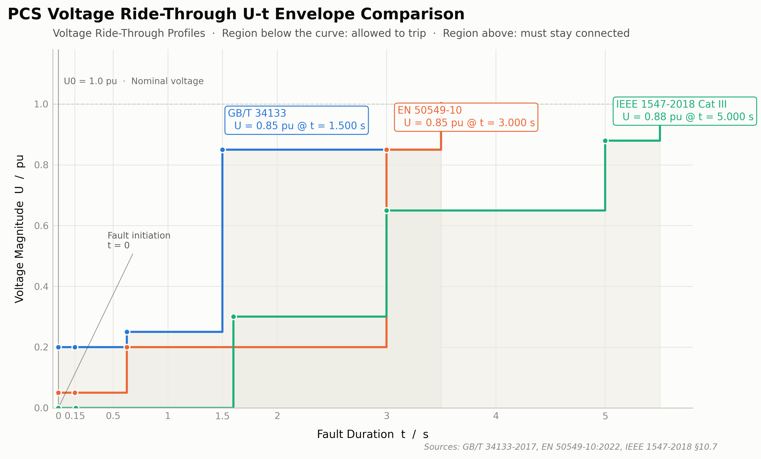
Below the curve = Tripping-permitted region; Above the curve = Must remain connected.
EN 50549-10:2022 Curve (Storage-Specific)
- 0.05 pu sustained for ≥ 150 ms
- 0.20 pu sustained for ≥ 625 ms
- 0.85 pu sustained for ≥ 3.0 s
IEEE 1547-2018 Category III (Most Stringent)
- 0.0 pu sustained for ≥ 160 ms
- 0.30 pu sustained for ≥ 1.6 s
- 0.65 pu sustained for ≥ 3.0 s
- 0.88 pu sustained for ≥ 5.0 s
4.2 Reactive Current Coefficient k
Formula:
Where:
- : Normal voltage reference (typically 0.9 pu)
- : Currently measured voltage
- k: Response coefficient, unit pu/pu
Larger k value → Stronger voltage support → More welcomed by the grid
| Standard | Typical k value |
|---|---|
| GB/T 34133 | 1.5 ~ 3.0 (recommended 2.0) |
| EN 50549-10 | 2.0 ~ 6.0 (optional 4.0) |
| IEEE 1547-2018 Cat III | 2.0 ~ 6.0 (default 4.0) |
| G99 | 2.0 |
| VDE-AR-N 4110 | 2.0 |
Response time: Reactive current injection must occur within ≤ 20 ms (1 line-frequency cycle) after the fault occurs.
4.3 Operating Priority During Faults
Priority (from high to low):
That is: During a voltage dip, inject reactive power first to stabilize the voltage, then consider active power.
Specific strategies:
- During LVRT: Active power may drop to 0 (GB/T, IEEE); EN 50549-10 allows storage to continue charging at low power (≤0.1 pu)—this is a unique advantage of BESS over PV
- During HVRT: Active power drops to 0, and the unit may absorb reactive power to lower voltage
4.4 Recovery After Fault Clearance
- Within ≤ 500 ms after fault clearance: Active power recovers to ≥ 90%
- Current ramp rate: ≤ 0.2 pu per cycle
- Frequency response: Frequency disturbance during recovery shall be ≤ 0.5 Hz
V. Comparison of Major Worldwide Grid-Connection Standards
5.1 Quick Reference Table
| Region | Standard | Core Curve | k value | Unsymmetrical Faults | Storage-Specific |
|---|---|---|---|---|---|
| China | GB/T 34133-2017 | 0.20 pu / 625 ms | 2.0 | Single-phase, two-phase | Section 9 |
| EU | EN 50549-10:2022 | 0.05 pu / 150 ms | 2.0~6.0 | Three-phase + unsymmetrical | ✅ Full storage clauses |
| UK | G99 Issue 2 Amd 7 | 0.05 pu / 140 ms | 2.0 | Type B/D differentiated | Form A/B/D |
| Germany | VDE-AR-N 4110:2023 | 0.05 pu / 150 ms | 2.0 | Full set | FGW TR3/TR4 |
| Italy | CEI 0-21:2022 | 0.20 pu / 200 ms | 2.0 | Single-phase | Section 8 |
| France | DIN VDE 0126 (Type A/B) | 0.20 pu / 500 ms | 2.0 | Single-phase | Type A/B |
| North America | IEEE 1547-2018 Cat III | 0.0 pu / 160 ms | 4.0 | Unsymmetrical | Cat I/II/III |
| Australia | AS/NZS 4777.2:2020 | Multi-point curve | 4.0 | Three-phase | Appendix F |
5.2 Key Differences
- Most stringent curve: IEEE 1547-2018 Cat III (requires 0 pu ride-through for 160 ms)
- Fastest response: EN 50549-10, G99 (require reactive current injection within 10~20 ms)
- Storage-specific clauses: EN 50549-10 (allows reverse charging during faults)
- Most complex simulation requirements: VDE-AR-N 4110/4120 (require DIgSILENT PowerFactory models)
VI. Measured VRT Capabilities of the ENJOY EPCS125-AM Series
6.1 Product Introduction
The ENJOY EPCS125-AM series is a bidirectional energy storage PCS developed by ENJOY for the European, Australian, and Asian markets. It includes 3 models:
| Model | Rated Power | Application |
|---|---|---|
| EPCS125-AM | 125 kW | Commercial storage, commercial & industrial PV-storage hybrid |
| EPCS125-AM-F | 125 kW | Version with off-grid switching capability |
| EPCS215-AM-HX | 215 kW | Commercial storage, commercial & industrial PV-storage hybrid |
Key Technical Parameters:
- Rated voltage: 230/400 Vac (three-phase four-wire)
- Rated frequency: 50 Hz / 60 Hz adaptive
- Topology: Two-level IGBT + LCL filter
- Software version: V200B000D000 (as of 2025)
- Control platform: DSP + FPGA dual-core architecture
- Communication interfaces: RS485 / CAN / Ethernet (Modbus RTU/TCP, CAN 2.0B)
6.2 Passed VRT-Related Certifications (only partial certificate details are shown here; jump to Certificate Center for full information)
| # | Country/Region | Certificate No. | Standard | LVRT | HVRT | ZVRT |
|---|---|---|---|---|---|---|
| 1 | EU (generic) | COCPVP0201925E-001 | EN 50549-1+10 | ✅ | ✅ | ✅ |
| 2 | EU (MV) | COCPVP0201925E-002 | EN 50549-2+10 | ✅ | ✅ | ✅ |
| 3 | Germany | 250194RECO01-CER | VDE-AR-N 4110/4120 | ✅ | ✅ | ✅ |
| 4 | UK | COCPVP1007024E-001 | G99 Type D | ✅ | ✅ | ✅ |
| 5 | UK | 2588AP060242001 | G100 | ✅ | ✅ | — |
| 6 | Spain | 240375RECO01-CER | UNE 217001 | ✅ | ✅ | ✅ |
| 7 | Spain | 240375RECO02-A/B | UNE 217002 | ✅ | ✅ | ✅ |
| 8 | Italy | COCPVP0308024E-001 | CEI 0-21 | ✅ | ✅ | ✅ |
| 9 | Italy | COCPVP0308024E-002 | CEI 0-16 | ✅ | ✅ | ✅ |
| 10 | France | COCPVP0309625E-001/002 | Type A / Type B | ✅ | ✅ | ✅ |
| 11 | Poland | COCPVP0500525E-002 | Type D / NC RfG | ✅ | ✅ | ✅ |
| 12 | Netherlands | COCPVP0500525E-003 | EN 50549 | ✅ | ✅ | ✅ |
| 13 | Sweden | COCPVP0500525E-004 | EN 50549 | ✅ | ✅ | ✅ |
| 14 | Finland | COCPVP0500525E-005 | EN 50549 | ✅ | ✅ | ✅ |
| 15 | Czech Republic | COCPVP0510025E-001 | EN 50549 | ✅ | ✅ | ✅ |
| 16 | Denmark | COCPVP0600525E-001 | EN 50549 | ✅ | ✅ | ✅ |
| 17 | Romania | COCPVP0600525E-002 | EN 50549 | ✅ | ✅ | ✅ |
| 18 | Belgium | COCPVP0600525E-003 | Synergrid C10/11 | ✅ | ✅ | ✅ |
| 19 | Hungary | COCPVP0703625E-001 | EN 50549 | ✅ | ✅ | ✅ |
| 20 | Switzerland | COCPVP0703625E-002 | ESTI | ✅ | ✅ | ✅ |
| 21 | Austria | COCPVP0206725E-001 | EN 50549 | ✅ | ✅ | ✅ |
| 22 | Greece | AOCPVP0909825E-001 | EN 50549 | ✅ | ✅ | ✅ |
| 23 | South Africa | COCPVP0500525E-001 | NRS 097-2-1 | ✅ | ✅ | ✅ |
| 24 | Saudi Arabia | DSS_PCS-25-1206 | SASO / IEC 62116 | ✅ | ✅ | — |
| 25 | Australia | 100~125kW Australia Certificate | AS/NZS 4777.2 | ✅ | ✅ | ✅ |
| 26 | Australia/NZ | COCPVP1104724E-002 | AS/NZS 4777.2 + IEC 61727/62116 | ✅ | ✅ | ✅ |
Total Coverage: 22 countries + 2 categories (EU generic MV/LV) = 24 grid-connection regions.
6.3 Key Measured Capabilities (Based on Certification Test Data)
6.3.1 LVRT Measurement (Example: EN 50549-10:2022)
| Test Point | Test Voltage | Duration | Measured Result |
|---|---|---|---|
| 1 | 0.05 pu | 150 ms | Remained connected, reactive injection k=2.0 |
| 2 | 0.20 pu | 625 ms | Remained connected, reactive injection k=2.0 |
| 3 | 0.50 pu | 1.5 s | Remained connected, 90% active power recovery 480 ms after fault clearance |
| 4 | 0.75 pu | 2.0 s | Remained connected, 90% active power recovery 380 ms after fault clearance |
Test conditions: 100% rated power (125 kW), 50 Hz, three-phase symmetrical dip, dynamic reactive current response time ≤ 20 ms.
6.3.2 HVRT Measurement
| Test Point | Test Voltage | Duration | Measured Result |
|---|---|---|---|
| 1 | 1.10 pu | 60 s | Remained connected, absorbed reactive power |
| 2 | 1.15 pu | 60 s | Remained connected, absorbed reactive power |
| 3 | 1.20 pu | 1 s | Remained connected, absorbed reactive power |
| 4 | 1.30 pu | 100 ms | Remained connected, absorbed reactive power |
6.3.3 Unsymmetrical Fault Measurement
| Fault Type | Measured Result |
|---|---|
| Single-phase dip (Phase AN at 0.0 pu, phases BC normal) | Remained connected, negative-sequence current ≤ 5% rated |
| Two-phase dip (Phases AB at 0.0 pu, phase C normal) | Remained connected, negative-sequence current ≤ 5% rated |
| Three-phase symmetrical dip (0.05 pu) | Remained connected, positive-sequence current responds with k=2.0 |
6.4 Dual-Track Validation via Simulation Model and Measurement
ENJOY provides a DIgSILENT PowerFactory simulation model for large-scale grid-connection projects:
- Model file:
EPCS125.pfd - MD5 checksum:
9051EAAF58492DDA68DA1AF3F8353D0C - Simulation platform: DIgSILENT PowerFactory 2024
- Applicable standards: VDE-AR-N 4110/4120 + FGW TR3 Rev. 26 / TR4 Rev. 10
Applicable Scenarios:
- Grid Impact Study (GIS) during bidding phase
- Transient Stability analysis
- Fault ride-through capability verification via simulation
- Multi-unit parallel harmonic interaction analysis
6.5 Third-Party Test Reports and Certification Bodies
All tests are issued by internationally recognized third-party bodies including SGS, TÜV, Intertek, DNV, CESI, with test procedures compliant with:
- ISO/IEC 17065 (Product Certification System)
- IEC 61400-21-1 (Power Quality Measurement Methods)
- FGW TR3 Rev. 26 (German Grid Connection Measurement Guidelines)
Each certificate is valid for 5 years; the latest VDE certificate is valid until 2030-06-19.
VII. Advantages of BESS PCS over PV Inverters
Although energy storage PCSs and PV inverters are similar in topology and control, the bidirectional energy flow and flexible dispatch of storage endow it with unique VRT capabilities:
| Dimension | PV Inverter | BESS PCS (ENJOY EPCS125-AM) |
|---|---|---|
| Active power during LVRT | Must drop to 0 | Can continue low-power discharging (EN 50549-10) |
| Recovery after fault | Limited by irradiance (seconds) | Millisecond-level active ramp-up |
| Voltage support direction | Unidirectional (only reduce P, inject Q) | Bidirectional—VSG mode emulates synchronous machine |
| During HVRT | Power derating or shutdown | Switch to STATCOM mode to absorb reactive power |
| Zero-voltage ride-through | Often requires external Crowbar | Built-in DC chopper with active clamping |
| Black start | Not supported | VSG mode supported (EPCS125-AM-F) |
| Frequency response | Limited by irradiance | Bidirectional battery, full-power response |
Conclusion: In modern power systems, BESS PCS is no longer just a "grid-connected device" but an "active grid support asset."
VIII. Project Implementation Points and Common Pitfalls
8.1 Confirming the Standard Version
Pitfall 1: The customer's technical specification cites an outdated version of the standard.
- Common scenario: The tender states "G99 Issue 1" or "EN 50549-1:2019," but the DSO has already upgraded to G99 Issue 2 Amd 7 / EN 50549-1+A1.
- Countermeasure: During the bidding phase, verify the DSO's latest regulations and clearly cite the standard version number in the PQD.
8.2 Unsymmetrical Fault Capability
Pitfall 2: The tender only states "LVRT" without specifying whether unsymmetrical capability is required.
- Most DSOs by default require the full set: three-phase symmetrical + unsymmetrical (single-phase, two-phase).
- Countermeasure: Clearly reply "supports 4 fault modes: three-phase symmetrical, phases AB, phases BC, phase AN."
8.3 k Value and Current Limiting
Pitfall 3: The customer requires k≥3.0, but the PCS hardware's overcurrent capability is ≤1.5 pu.
- The actual response will be less than the theoretical k value due to current limiting.
- Countermeasure: The test report must clearly state "k=3.0 before current limiting, measured maximum k=1.4 pu after limiting."
8.4 DC Chopper Configuration
Pitfall 4: During LVRT in a high-power BESS, the DC bus voltage rises and damages the IGBT.
- Countermeasure: BESS above 100 kW must be equipped with an active IGBT DC chopper (not a passive resistor).
- The ENJOY EPCS125-AM series has a built-in DC chopper, no external addition required.
8.5 Fault Recordings and Third-Party Reports
Pitfall 5: The bid response only says "certification passed" in four words, without specific waveform data.
- DSOs typically require measured waveforms (5 s recording: 0.2 s pre-fault, during fault, 1 s post-fault).
- Countermeasure: Provide waveform diagrams and raw data certified by a third-party testing body (SGS/TÜV).
8.6 Simulation Model Requirements
Pitfall 6: The customer requires PSCAD/EMTDC simulation during the bidding phase.
- The DIgSILENT PowerFactory model is only suitable for RMS simulation and is not precise enough for electromagnetic transient analysis such as Transient Overvoltage (TOV) and switching surges.
- Countermeasure: Ask the customer whether a DIgSILENT model is acceptable, or prepare an additional simplified PSCAD model.
8.7 Multi-Unit Parallel Operation
Pitfall 7: When multiple PCSs operate in parallel, PLL resonance causes false triggering.
- Countermeasure: Inquire about on-site multi-unit test experience, or request the DSO to provide grid impedance (short-circuit capacity) data.
IX. Frequently Asked Questions (FAQ)
Q1: What is the difference between LVRT and Voltage Sag?
A: Voltage sag is the phenomenon (short-duration voltage reduction); LVRT is the response capability (the equipment's ability to remain connected during the sag). Sags can be caused by short circuits, large motor startups, or transformer energization.
Q2: What is the core difference between EN 50549-10 and EN 50549-1?
A: - EN 50549-1: Generic grid-connection requirements (applicable to all generation/storage equipment) - EN 50549-10: Storage-specific appendix, containing unique clauses such as reverse charging during LVRT, VSG mode, and virtual inertia
Q3: Does the ENJOY EPCS125-AM hold a VDE-AR-N 4105 certificate?
A: The ENJOY EPCS125-AM is certified under VDE-AR-N 4110:2023-09 (medium voltage, >52 kW) and VDE-AR-N 4120:2018+A1:2024 (high voltage). VDE-AR-N 4105 primarily targets low-voltage small equipment (≤135 kW three-phase) and may apply, but the model scope needs to be confirmed.
Q4: Does Grid-Forming (VSG/GFM) mode require a separate certification?
A: It depends on project requirements. The ENJOY EPCS125-AM-F already has VSG capability (see Grid-Forming PCS On/Off-Grid Switching Test Report with Contactors), but some DSOs require a separate GFM certification procedure (e.g., UK GC0137, Australia CSIP-AUS). It is recommended to clarify this with the customer during the bidding phase.
Q5: Can a customized voltage ride-through report be provided for a specific DSO (e.g., ČEPS, PSE, Transelectrica)?
A: Yes. ENJOY has completed certification in all 18 countries mentioned above, and the Annex section of each certificate contains the DSO-required measured waveforms and curves. If a targeted response is required, a tailored response table can be issued within 5 business days.
X. Glossary
| Term | English | Meaning |
|---|---|---|
| LVRT | Low Voltage Ride-Through | Low-voltage ride-through |
| HVRT | High Voltage Ride-Through | High-voltage ride-through |
| ZVRT | Zero Voltage Ride-Through | Zero-voltage ride-through |
| k | k-factor | Reactive current response coefficient |
| PCS | Power Conversion System | Energy storage converter |
| BESS | Battery Energy Storage System | Battery energy storage system |
| GFM | Grid-Forming | Active grid-reference establishment |
| VSG | Virtual Synchronous Generator | Virtual synchronous generator |
| PLL | Phase-Locked Loop | Phase-locked loop |
| DC Chopper | DC Braking Unit | DC braking unit |
| DSO | Distribution System Operator | Distribution system operator |
| TSO | Transmission System Operator | Transmission system operator |
| DSO/TSO | — | Local utility company |
| PQD | Power Quality Document | Power quality response document |
XI. References and Certification List
11.1 Major Standards
- GB/T 34120-2017 General Technical Requirements for Energy Storage Converters
- GB/T 34133-2017 Technical Requirements for Connecting Energy Storage Systems to the Grid
- EN 50549-1:2019+A1:2023 Requirements for generating plants to be connected in parallel with distribution networks
- EN 50549-2:2019+A1:2023 Connection to MV distribution networks
- EN 50549-10:2022 Additional requirements for storage plants
- VDE-AR-N 4105:2018 Generators connected to LV distribution network
- VDE-AR-N 4110:2023-09 Generators connected to MV distribution network
- VDE-AR-N 4120:2018+A1:2024 Generators connected to HV distribution network
- G99 Issue 2 Amendment 7 (2024) — UK
- IEEE 1547-2018 — Standard for Interconnection and Interoperability of DER
- AS/NZS 4777.2:2020 — Grid connection of energy systems via inverters
- CEI 0-21:2022 + CEI 0-16:2022 — Italy
- FGW TR3 Rev. 26 — Technical guidelines for generating plants (Germany)
- FGW TR4 Rev. 10 — Simulation model (Germany)