
In-Depth Technical Analysis of the Four Major PCS Control Modes
PQ · VF · VSG · Grid-Following (GFL) · Grid-Forming (GFM)
1 Panoramic Quick View
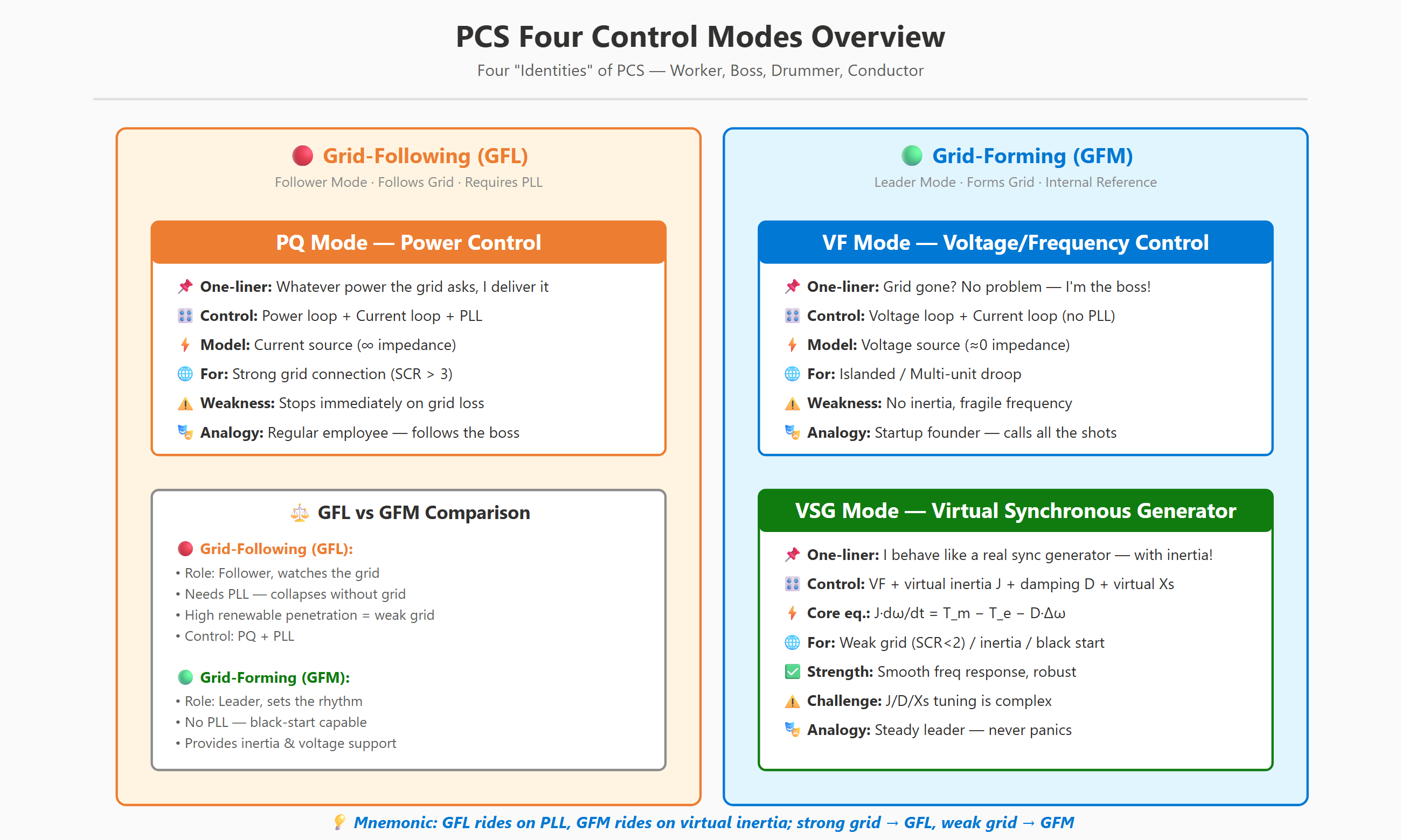
1.1 Core Comparison
| Mode | Role | Control Objective | Follows Whom | Grid Dependency |
|---|---|---|---|---|
| PQ Grid-Following | Worker | Output P/Q | Grid | Very strong |
| VF Islanded | Boss | Output U/f | Internal reference | None |
| VSG Grid-Forming | Steady Boss | Output U/f + inertia | Self inertia | None |
| GFM (general term) | Active support | VF + VSG + droop | Self | Weak |
| GFL (general term) | Passive follower | PQ + PLL | Grid | Strong |
Mnemonic: Grid-following relies on phase-locking, grid-forming relies on virtual synthesis; when the grid is strong use grid-following, when the grid is weak use grid-forming.
2 Why Does a PCS Need "Multiple Identities"?
The awkward position of an energy-storage PCS: to whom does the "controllable" output ultimately listen?
- Listen to the grid → Worker (PQ)
- Listen to itself → Boss (VF)
- Dress up as the fighter-jet version of the Boss → VSG
| Choice | Physical Essence | Analogy |
|---|---|---|
| Grid-Following PQ | Current source (high internal impedance) | Worker |
| Grid-Forming VF | Voltage source (low internal impedance) | Boss |
| Grid-Forming VSG | Voltage source + flywheel | Steady Boss |
2 PQ Mode (Worker)
"Boss (the grid) tells me how much power, I output exactly that much power"
2.1 Control Architecture
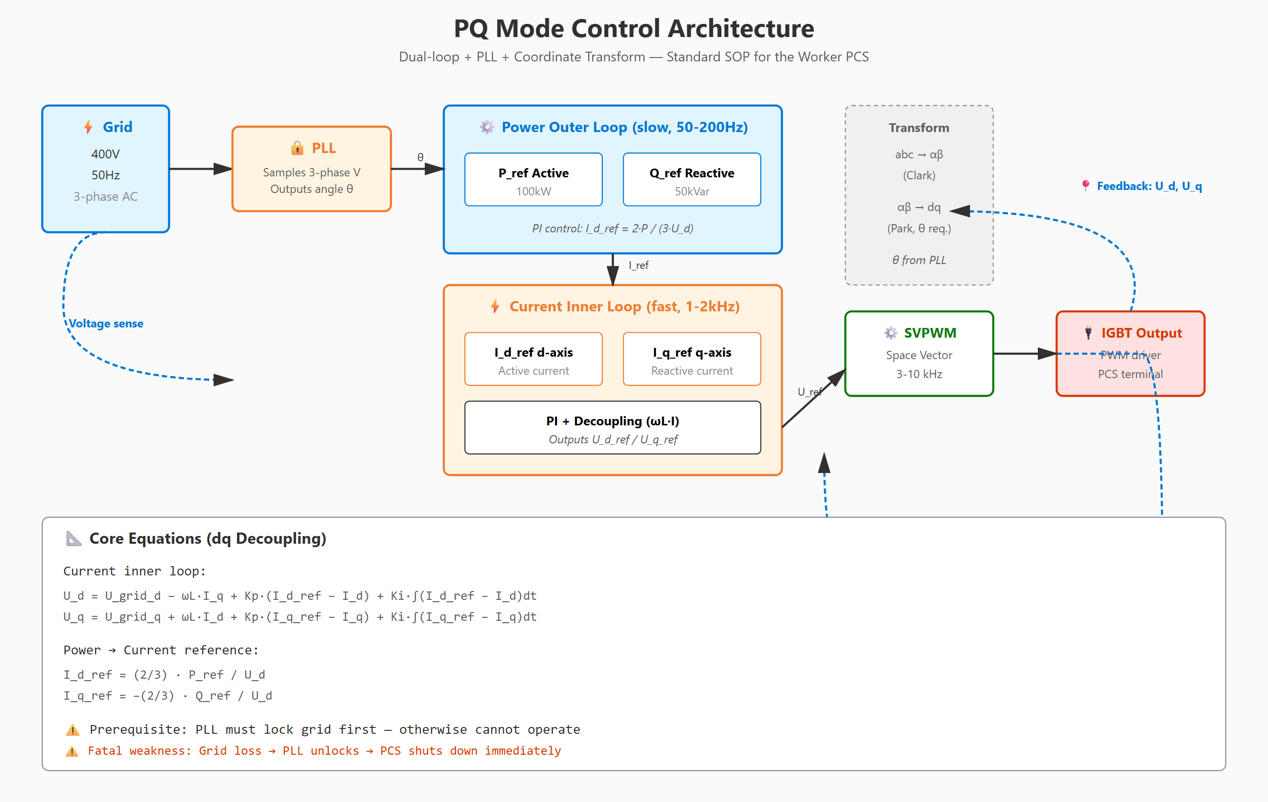 PQ mode adopts the classic "dual-loop + PLL" structure: outer power loop + inner current loop + phase-locked loop. The PLL is the key; without it the mode cannot operate.
2.2 PLL's Fatal Weakness
| Grid Condition | PLL Behavior | PCS Impact |
|---|---|---|
| Ideal grid | ✅ Locks quickly | Normal operation |
| Harmonic distortion | ⚠️ Jitters | Power oscillation |
| Weak grid, SCR < 2 | ❌ Loses lock | Mode fails |
| Complete grid outage | ❌ No signal | PCS shuts down |
2.3 Applicable Scenarios
✅ Grid connection to a strong grid (SCR > 3), AGC/AVC dispatch response, peak shaving and valley filling ❌ Not suitable for weak grids or black-start
3 VF Mode (Boss)
"Grid is gone? No problem, I'll be the boss!"
3.1 Control Architecture
VF mode has no PLL; it directly uses an internal reference (U = 400 V, f = 50 Hz) as the voltage source. Voltage outer loop + current inner loop achieves constant voltage and constant frequency.
3.2 Multi-Unit Paralleling: Droop Control
Multiple PCSs require only communication to automatically share power. Principle: when output is higher, frequency/voltage droops slightly → automatic balance.
Tuning Principle: droop coefficient × rated capacity of every PCS must be equal → only then is power sharing achieved.
3.3 Hard Constraints of VF
- Load < PCS capacity (otherwise voltage collapses)
- Short-circuit current only 1.2–1.5× (no inertia)
- Fixed frequency (no governor)
- Poor resilience to impact loads (undamped second-order system)
3.4 Applicable Scenarios
✅ Microgrid islanded operation, black-start, UPS mode, master-slave switching of multiple PCSs ❌ Not suitable for scenarios requiring inertia support
4 VSG — Virtual Synchronous Generator (the Steady Boss)
"I pretend to be a real synchronous generator, with inertia!"
4.1 Core Idea
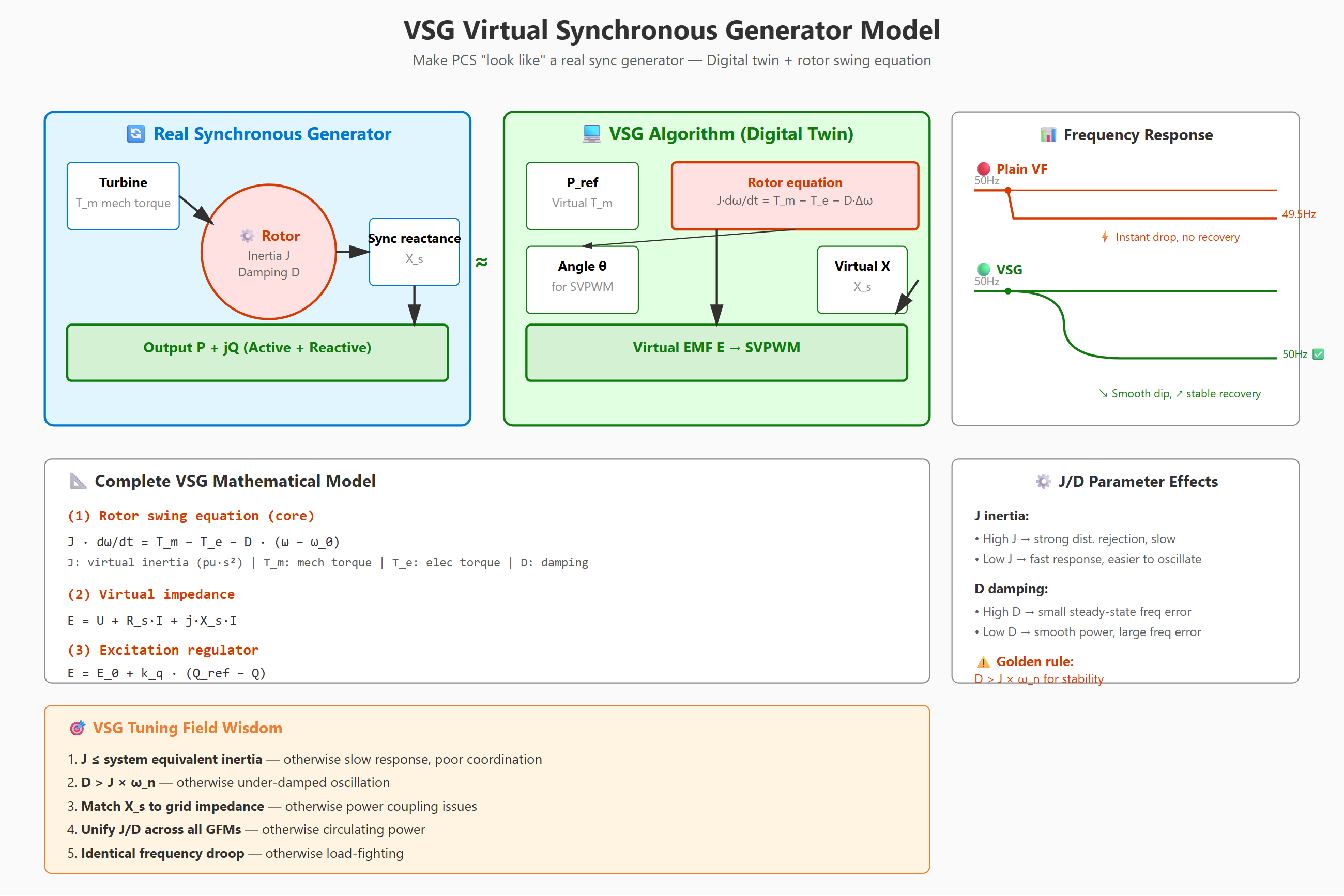
Inside the VSG there is a virtual flywheel that emulates the rotor motion of a synchronous generator, making the PCS behave like a real generator.
| Real Synchronous Machine | VSG Algorithm |
|---|---|
| Physical flywheel | Software parameter J (pu·s²) |
| Physical damper | Software parameter D (pu·s/rad) |
| Synchronous reactance | Virtual reactance X_s (pu) |
| Excitation system | Software excitation regulator |
| Governor | Software droop |
4.2 Complete Mathematical Model
(1) Rotor motion equation (core): J × angular acceleration = mechanical torque − electromagnetic torque − damping × frequency deviation
(2) Virtual impedance: EMF = terminal voltage + virtual impedance × current
(3) Excitation regulation: EMF = initial value + reactive-droop coefficient × (Q_ref − Q)
(4) Governor: mechanical torque = initial value + active-droop coefficient × (P_ref − P)
4.3 Influence of J / D / X_s Parameters
| Parameter | Large | Small |
|---|---|---|
| J (inertia) | Strong disturbance rejection / slow response | Fast response / prone to instability |
| D (damping) | Small steady-state deviation / large power oscillation | Smooth power / large frequency deviation |
| X_s (reactance) | Good power decoupling / large voltage drop | Strong voltage support / power coupling |
4.4 Frequency-Response Comparison
- 🔴 VF: on a sudden load change it drops instantly to 49.5 Hz, may trip
- 🟢 VSG: drops gradually to 49.8 Hz over 0.5 s, then recovers smoothly
The VSG's "dip slowly and recover" buys time for grid equipment to react — this is the value of inertia.
4.5 Golden Rules of Tuning
- J must not exceed the system's equivalent inertia — otherwise frequency response is too slow
- D must be greater than J × angular speed — otherwise underdamped oscillation ⚠️
- X_s must match the grid impedance — otherwise power coupling
- J/D of all GFM units must be coordinated — otherwise power circulating currents between parallel units
- Frequency-droop coefficient must be uniform across the whole grid — otherwise power-grabbing
4.6 Applicable Scenarios
✅ Connection to weak grids (SCR < 2), high-renewable-penetration areas, black-start, islanded microgrids, frequency and peak regulation
5 Grid-Forming vs. Grid-Following
5.1 System Evolution Trend
In the renewable era, grid-following converters are proliferating, and the grid is becoming increasingly fragile. Grid-forming energy storage is the solution.
5.2 Core Comparison
| Dimension | 🔴 Grid-Following (GFL) | 🟢 Grid-Forming (GFM) |
|---|---|---|
| Physical model | Current source | Voltage source |
| PLL dependency | Required | Not required |
| Short-circuit current | < 1.2× | 1.5–3× |
| Frequency response | Only power regulation | Directly influences frequency |
| Inertia support | ❌ None | ✅ Yes |
| Black-start | ❌ Cannot | ✅ Can |
| SCR requirement | SCR ≥ 2–3 | Works with SCR < 1 |
5.3 Grid Strength (SCR) vs. Control Mode
| SCR | Recommended Mode | Cost |
|---|---|---|
| > 5, very strong | PQ is fully OK | ⭐ |
| 3–5, strong | PQ is usable | ⭐⭐ |
| 2–3, medium | PQ carries risk, GFM recommended | ⭐⭐⭐ |
| < 2, weak | GFM mandatory, VSG provides strong support | ⭐⭐⭐⭐ |
| < 1.5, very weak | VSG mandatory | ⭐⭐⭐⭐⭐ |
6 Terminology Quick-Reference Table
| Abbreviation | Full Name | Meaning in One Line |
|---|---|---|
| PLL | Phase Locked Loop | The "ear" that listens to the grid's rhythm |
| SCR | Short Circuit Ratio | How strong the grid is |
| d/q axis | d/q axis | The two DC components after decomposing three-phase AC |
| J | Virtual Inertia | The flywheel weight of the VSG |
| D | Damping | The shock absorber of the VSG |
| X_s | Virtual Reactance | The virtual internal resistance of the VSG |
| SVPWM | Space Vector PWM | The switching algorithm that converts DC to AC |
| SoC | State of Charge | The battery's fuel gauge |
| EMS | Energy Management System | The brain of the energy-storage system |
| STS | Static Transfer Switch | The fast on-grid/off-grid gate |
| GFM | Grid-Forming | Be the grid yourself |
| GFL | Grid-Following | Follow the grid |
| VSG | Virtual Synchronous Generator | Pretend to be a synchronous generator |
| LVRT | Low Voltage Ride-Through | Withstand voltage dips without disconnecting |
| PQ | Power Control | Controls only active/reactive power |
| VF | Voltage/Frequency Control | Controls voltage and frequency |