
30-Second Overview
One-liner: Use STS for grid/battery second-level switching + PCS for grid-forming off-grid operation, so that the energy storage cabinet replaces or down-configures the traditional UPS + diesel generator.
0.1 Core Selling Points
- Switching time ≤ 20 ms — faster than ATS, seamless transfer
- Single system 125 kW ~ 750 kW, up to 6 cabinets in parallel
- Off-grid operation ≥ 2 h (battery capacity scalable, stackable up to 8 h)
- Replace / down-configure diesel generators, saving fuel and O&M
0.2 Four-Step Sizing Path
| Step | What to Do | Reference |
|---|---|---|
| 1 | Clarify the load (power / type / backup duration) | Customer input |
| 2 | Check R1–R6 to determine the loading ratio | §7.1 |
| 3 | Calculate cabinet count + select STS | §5 + §6 |
| 4 | Verify charging STS + one-shot load pickup | §7.3 |
0.3 Five Red-Line Rules at a Glance
- BESS charging power + load power ≤ STS (maximum operating power)
- Multi-module one-shot load pickup ≤ 40%
- Off-grid cosφ ≥ 0.8
- Inductive / tungsten / EV chargers → DyN11 required
- 6 cabinets is the off-grid loading upper limit
1 Applicable Products
1.1 ENJOY Series
| Type | Model | Capacity |
|---|---|---|
| STS | ESTS250-M (ESTS250-S) | 250 kW |
| STS | ESTS500-M (ESTS500/1000-S) | 500 kW |
| PCS | EPCS125-AM (D-Cube-A250/375/500) | 125 kW |
| PCS | EPCS125-AM-F (D-Cube-S125/261-EU) | 125 kW |
1.2 Hoenergy Series
| Type | Model | Capacity |
|---|---|---|
| STS | ESTS250-S | 250 kW |
| STS | ESTS500-S | 500 kW |
| STS | ESTS1000-S | 1000 kW |
| All-in-one BESS Cabinet | D-Cube-S125/261-EU | 125 kW / 261 kWh (liquid-cooled) |
| PCS All-in-one Cabinet | D-Cube-A250 | 250 kW |
| PCS All-in-one Cabinet | D-Cube-A375 | 375 kW |
| PCS All-in-one Cabinet | D-Cube-A500 | 500 kW |
| Battery Cabinet | D-Cube-261D | 261 kWh (paired with A series) |
2 System Composition
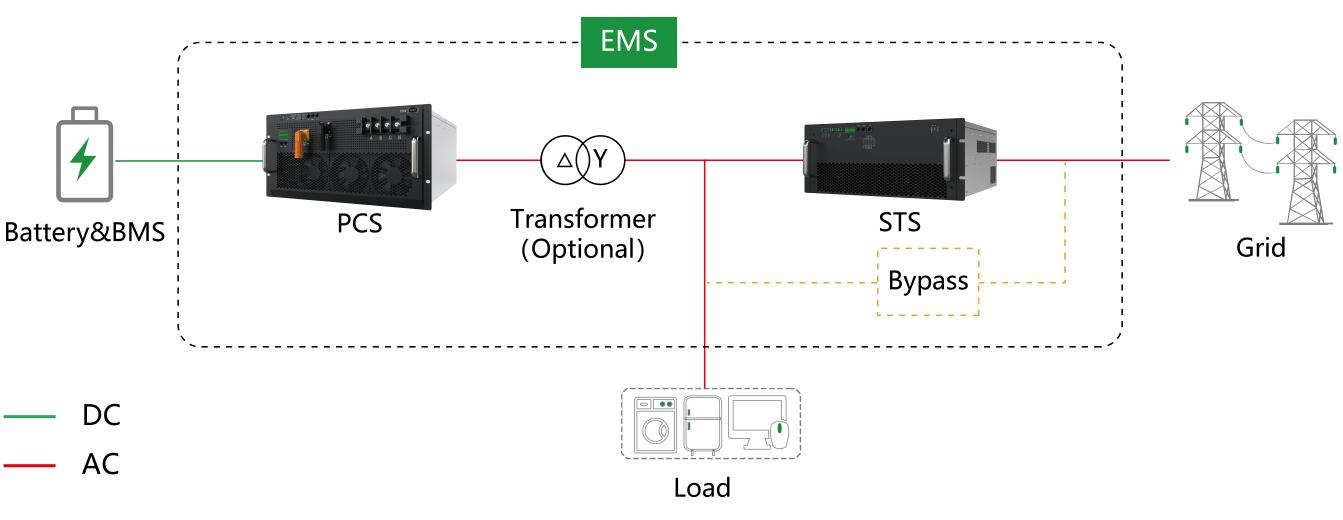
2.1 Topology A: One STS + One PCS
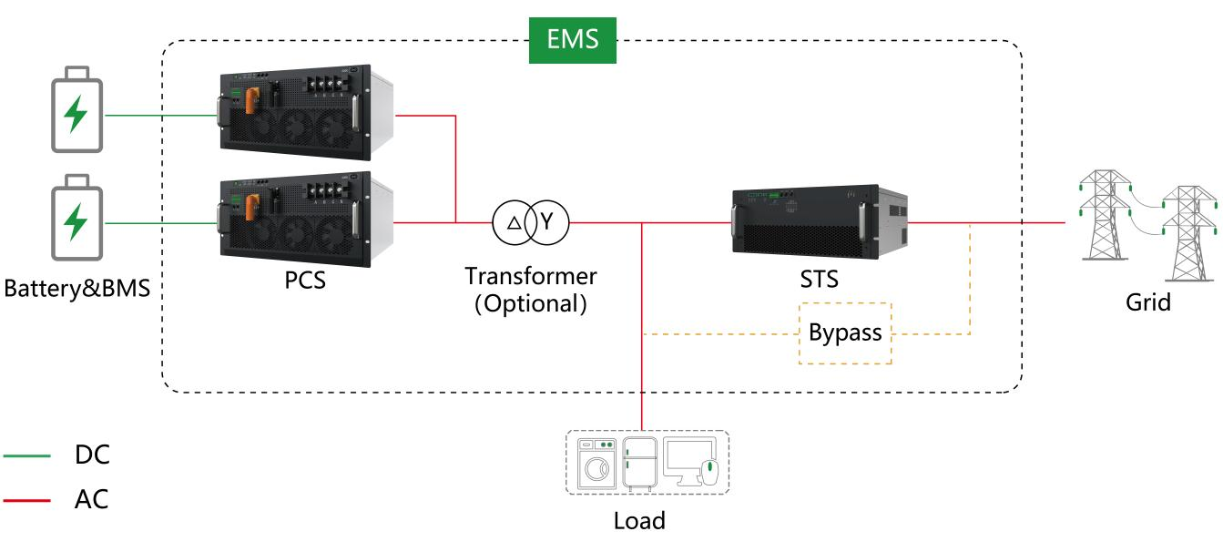
2.2 Topology B: One STS + Multiple PCS (one battery cluster per management unit)
2.3 Responsibilities of the Three Major Components
| Component | Function |
|---|---|
| STS Static Transfer Switch | Monitors grid status in real time; quickly disconnects the grid on abnormality to prevent islanding and back-feeding |
| PCS Power Conversion System | In grid-connected mode runs grid-following (PQ mode); in off-grid mode runs grid-forming (VF mode) |
| Bypass Bypass Switch | Closed during STS maintenance, open at all other times |
| Battery System + BMS | Stores electrical energy; provides SoC / SoH / cell status data; safeguards safety boundaries |
3 Operating Modes
3.1 Mode 1 | Grid-Connected Operation (Normal)
- Load is powered by the grid
- The BESS executes economic tasks such as peak shaving / demand management / frequency regulation per EMS strategy
- PCS works in grid-following mode
3.2 Mode 2 | Off-Grid Transfer (At the Moment of Fault)
- STS detects that mains voltage/frequency is out of limits or power is lost
- STS disconnects the grid side (millisecond level)
- PCS switches from grid-following to grid-forming (VF) mode and actively establishes voltage and frequency
- The load continues to operate without perception
3.3 Mode 3 | Off-Grid Supply (Continuous)
- PCS acts as the sole power source, independently supporting the load
- Supply duration = available energy ÷ load power (e.g., 1 cabinet 261 kWh with 100 kW load ≈ 2.3 h)
- If PV is present on-site, it can form a microgrid with PV to extend endurance
3.4 Mode 4 | Grid Reconnection
- STS detects that the grid has recovered and stabilized (configure the grid-reconnection time — within how long phase adjustment completes and the off-grid-to-grid transition is performed)
- PCS synchronizes and smoothly connects; load is transferred back to mains
- The BESS switches to charging to prepare for the next outage
4 Typical Application Scenarios
| Scenario | Pain Point | Solution Value |
|---|---|---|
| Data centers / telecom base stations | Outage = business interruption | Millisecond-level takeover, replacing or down-configuring UPS and diesel generators |
| Precision manufacturing / semiconductor | A single transient causes the entire batch to be scrapped | Protects critical processes, avoids high losses |
| Hospitals / commercial complexes | Emergency lighting, elevators, fire protection must keep power | Meets guaranteed-load supply requirements |
| Factories in weak-grid areas | Frequent outages, unstable voltage | Improves supply reliability, stabilizes production |
| Off-grid / weak-grid microgrids | No mains or unreliable mains | PV + BESS builds an independent supply system |
5 Recommended Product Configuration Table
The configuration table only provides recommendations for standard scenarios. Specific selection must be based on load type, operating scenario, etc., and verified per Section 6.
STS power = BESS charging power + load operating power
Single-phase load upper limit = min (PCS total rating × loading ratio, PCS total rating ÷ 3)
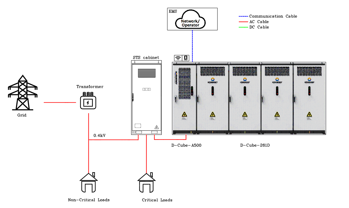
5.1 ESTS + D-Cube-A Series + 261D
| Grid Side (STS Total Power) | AC Side (PCS Total Power) | 2 h Backup | 4 h Backup | 6 h Backup | 8 h Backup |
|---|---|---|---|---|---|
| ESTS500-S (500 kW) | 1 × D-Cube-A250 (250 kW) | 2 × 261D (522 kWh) | 4 × 261D (1044 kWh) | 6 × 261D (1566 kWh) | 8 × 261D (2088 kWh) |
| ESTS1000-S (1000 kW) | 1 × D-Cube-A375 (375 kW) | 3 × 261D (783 kWh) | 6 × 261D (1566 kWh) | 9 × 261D (2349 kWh) | 12 × 261D (3132 kWh) |
| ESTS1000-S (1000 kW) | 1 × D-Cube-A500 (500 kW) | 4 × 261D (1044 kWh) | 8 × 261D (2088 kWh) | 12 × 261D (3132 kWh) | 16 × 261D (4176 kWh) |
| ESTS1000-S (1000 kW) | 1 × A375 + 1 × A250 (625 kW) | 5 × 261D (1305 kWh) | 10 × 261D (2610 kWh) | 15 × 261D (3915 kWh) | 20 × 261D (5220 kWh) |
| ESTS1000-S (1000 kW) | 2 × D-Cube-A375 (750 kW) | 6 × 261D (1566 kWh) | 12 × 261D (3132 kWh) | 18 × 261D (4698 kWh) | 24 × 261D (6264 kWh) |
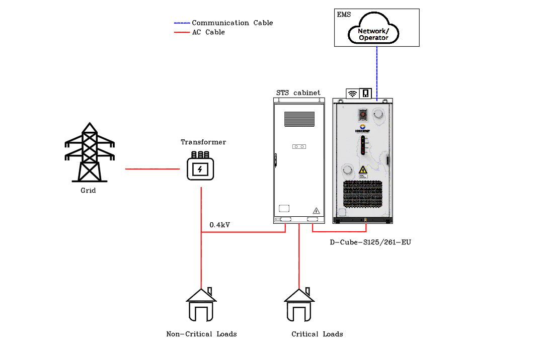
5.2 ESTS + D-Cube-S125/261-EU Series
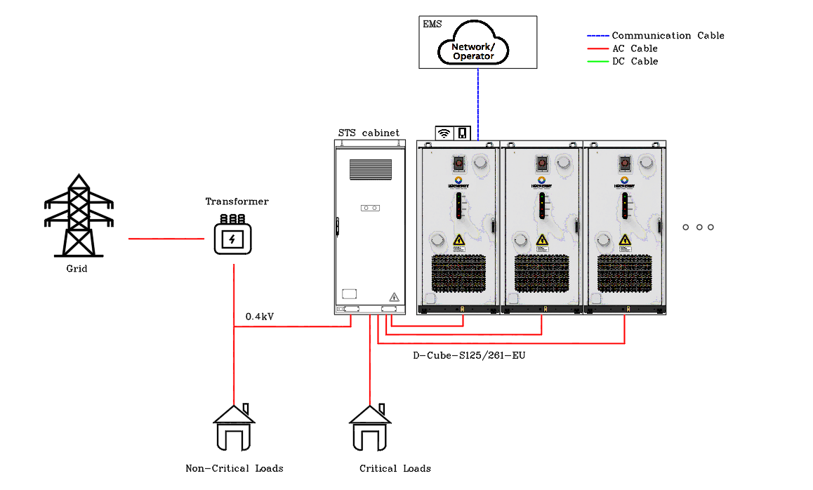
| Grid Side (STS Total Power) | AC Side | PCS Rated Power | Battery Capacity |
|---|---|---|---|
| ESTS250-S (250 kW) | 1 × D-Cube-S125/261-EU | 125 kW | 261 kWh |
| ESTS500-S (500 kW) | 2 × D-Cube-S125/261-EU | 250 kW | 522 kWh |
| ESTS1000-S (1000 kW) | 3 × D-Cube-S125/261-EU | 375 kW | 783 kWh |
| ESTS1000-S (1000 kW) | 4 × D-Cube-S125/261-EU | 500 kW | 1044 kWh |
| ESTS1000-S (1000 kW) | 5 × D-Cube-S125/261-EU | 625 kW | 1305 kWh |
| ESTS1000-S (1000 kW) | 6 × D-Cube-S125/261-EU | 750 kW | 1566 kWh |
6 Configuration Sizing Formulas and Quick Reference
6.1 Core Formula
STS Power ≥ BESS Charging Power + Load Operating Power
This hard constraint must be satisfied under all operating conditions; otherwise the STS will overload and trip.
6.2 Scenario Quick Reference
| Scenario | BESS Cabinet Count | Recommended STS | Recommended Loading (Resistive 80%) | Max One-Shot Load Pickup |
|---|---|---|---|---|
| Small shop / villa | 1 unit | 1 × 250 kW | 100 kW | 50 kW |
| Medium shop / small office | 1–2 units | 1 × 500 kW | 200–300 kW | 100 kW |
| Commercial complex | 2–3 units | 1×250 + 1×500 parallel | 300–400 kW | 150 kW |
| Small factory | 3–4 units | 2 × 500 kW parallel | 400–500 kW | 200 kW |
| Medium factory | 4–5 units | 2 × 500 kW parallel | 300–500 kW | 250 kW |
| Large factory (fully configured) | 6 units | 2 × 500 kW parallel | 200–600 kW | 300 kW |
See §7.1 R1–R6 for detailed load type restrictions; the complete product configuration matrix is in §7.2–§7.3.
6.3 Load Type Quick Reference Entry
| Load Type | Max Loading Ratio | Key Restriction | See |
|---|---|---|---|
| Pure resistive (electric heating, incandescent lamps) | ≤ 100%, recommended 80% | Most friendly | R1 |
| VFD-driven (inverter AC / pumps) | ≤ 60% (with mixed lighting ≤ 70%) | Starting current must be calculated | R3 |
| Inductive / impact (direct-on-line motor, fixed-frequency AC) | ≤ 15–20% | High inrush current, must derate | R2 |
| Tungsten lamps / AC EV chargers | DyN11 isolation transformer required | Prevents DC component triggering insulation alarm | R4 |
7 Off-Grid Load Loading Rules R1–R6
Applicable to equipment using ENJOY 125 kW PCS: D-Cube-S125/261-EU, D-Cube-A250/375/500. Formula: STS Power = BESS Charging Power + Load Operating Power
7.1 Complete Rules R1–R6
| Rule | Original Text (Excerpt) | Engineering Meaning | Typical Loads |
|---|---|---|---|
| R1 | Pure resistive load power ≤ PCS rated power, supports 100% loading capability, recommended at 80% loading ratio | Resistive heating, incandescent lamps, electric water heaters, etc., with an upper loading ratio of 80% | Electric boilers, electric water heaters, incandescent lamps |
| R2 | Pure inductive load power ≤ 15%~20% of PCS rated power (direct-on-line motors, water pumps, electric drills, non-inverter AC, and other impact loads) | Starting current is 6–8× rated; deep derating + soft start required | Direct-on-line motors, water pumps, electric drills, non-inverter AC |
| R3 | VFD-type load power ≤ 60% of PCS rated power; inverter AC + lighting and other conventional loads ≤ 70% of PCS rated power | VFDs have rectifier harmonics; derate to 60–70% | Inverter AC, inverter pumps, inverter elevators |
| R4 | Special loads (high power-quality requirement loads, such as theater tungsten lamps, AC EV chargers, etc.) require a DyN11 isolation transformer at the PCS AC output to enhance reliability and anti-interference | DyN11 isolation transformer resists harmonics + impact + provides electrical isolation | Theater tungsten lamps, AC EV chargers, medical equipment |
| R5 | In PCS off-grid mode, power factor ≥ 0.8 (pure resistive load); ● Single module one-shot pickup can support 100% connect/disconnect, recommended 80% ● Multi-module startup off-grid one-shot pickup rate ≤ 40%, remaining load is connected slowly ● Special application solutions require detailed confirmation of the design scheme and load characteristics with our technical staff |
Hard constraint for off-grid paralleling; violation triggers PCS protection or inter-module circulating current | All off-grid / microgrid scenarios |
| R6 | Single phase must also adapt to the above restrictions (R1–R5), supports unbalanced loading at 100%, single-phase rated power = 1/3 PCS rated power | Three phases can be fully unbalanced; single-phase physical upper limit = PCS/3 | Single-phase high-power loads, single-phase EV chargers, single-phase AC |
7.2 BESS × STS Basic Configuration Matrix (R1 / R5 / R6)
| BESS Cabinet Count | PCS Total Rating | Recommended STS Config | STS Total Rating | Three-Phase Max Discharge (R1: 80%) | Single-Phase Max Discharge (R6: PCS/3) | One-Shot Pickup (R5) |
|---|---|---|---|---|---|---|
| 1 unit | 125 kW | 1 × 250 kW | 250 kW | 100 kW | 41.67 kW | Single module 100%, recommended 80% (100 kW) |
| 1 unit | 125 kW | 1 × 500 kW | 500 kW | 100 kW | 41.67 kW | Single module 100%, recommended 80% (100 kW) |
| 2 units | 250 kW | 1 × 500 kW | 500 kW | 200 kW | 83.33 kW | Multi-module ≤ 40% (≤ 100 kW) |
| 3 units | 375 kW | 1 × 500 kW | 500 kW | 300 kW | 125 kW | Multi-module ≤ 40% (≤ 150 kW) |
| 4 units | 500 kW | 1 × 500 kW | 500 kW | 400 kW | 166.67 kW | Multi-module ≤ 40% (≤ 200 kW) |
| 5 units | 625 kW | 2 × 500 kW parallel | 1000 kW | 500 kW | 208.33 kW | Multi-module ≤ 40% (≤ 250 kW) |
| 6 units | 750 kW | 2 × 500 kW parallel | 1000 kW | 600 kW | 250 kW | Multi-module ≤ 40% (≤ 300 kW) |
R5 Applicable: For all BESS cabinet counts, off-grid operation requires cosφ ≥ 0.8 (pure resistive load). R6 Applicable: Single-phase physical hard upper limit = PCS/3; meanwhile three phases can be fully unbalanced to 100% single-phase loading.
7.3 Three-Phase Balanced / Single-Phase Unbalanced Load Discharge Limits (R1–R5 / R6)
7.3.1 Three-Phase Balanced Load
| BESS Cabinet Count | PCS Total Rating | R1 Pure Resistive ≤100%/Rec.80% | R2 Pure Inductive ≤15–20% | R3 VFD-Type ≤60% | R3 VFD + Lighting ≤70% | R4 Special Load Tungsten/AC EV Charger |
|---|---|---|---|---|---|---|
| 1 unit | 125 kW | 100 kW | 19–25 kW | 75 kW | 87.5 kW | DyN11 Required |
| 2 units | 250 kW | 200 kW | 38–50 kW | 150 kW | 175 kW | DyN11 Required |
| 3 units | 375 kW | 300 kW | 56–75 kW | 225 kW | 262.5 kW | DyN11 Required |
| 4 units | 500 kW | 400 kW | 75–100 kW | 300 kW | 350 kW | DyN11 Required |
| 5 units | 625 kW | 500 kW | 94–125 kW | 375 kW | 437.5 kW | DyN11 Required |
| 6 units | 750 kW | 600 kW | 113–150 kW | 450 kW | 525 kW | DyN11 Required |
7.3.2 Single-Phase Unbalanced Load (R6 + R1–R5)
R6 Key: Single-phase physical hard upper limit = PCS total rating / 3; meanwhile the single phase must also comply with R1–R5 restrictions. Single-Phase Load Upper Limit = min (PCS total rating × loading ratio, PCS total rating / 3)
| BESS Cabinet Count | PCS Total Rating | Single-Phase Physical Limit R6: PCS/3 | R1+R6 Single-Phase Pure Resistive min(80%, PCS/3) | R2+R6 Single-Phase Pure Inductive min(20%, PCS/3) | R3+R6 Single-Phase VFD min(60%, PCS/3) | R3+R6 Single-Phase VFD + Lighting min(70%, PCS/3) |
|---|---|---|---|---|---|---|
| 1 unit | 125 kW | 41.67 kW | 33.33 kW (80%) | 8.33 kW (20%) | 25 kW (60%) | 29.17 kW (70%) |
| 2 units | 250 kW | 83.33 kW | 66.67 kW (80%) | 16.67 kW (20%) | 50 kW (60%) | 58.33 kW (70%) |
| 3 units | 375 kW | 125 kW | 100 kW (80%) | 25 kW (20%) | 75 kW (60%) | 87.5 kW (70%) |
| 4 units | 500 kW | 166.67 kW | 133.33 kW (80%) | 33.33 kW (20%) | 100 kW (60%) | 116.67 kW (70%) |
| 5 units | 625 kW | 208.33 kW | 166.67 kW (80%) | 41.67 kW (20%) | 125 kW (60%) | 145.83 kW (70%) |
| 6 units | 750 kW | 250 kW | 200 kW (80%) | 50 kW (20%) | 150 kW (60%) | 175 kW (70%) |
R6 Interpretation: Supports 100% unbalanced three-phase loading — for example, with 6 units of 750 kW PCS, phase A fully loaded at 250 kW, phases B/C unloaded, the PCS can still operate normally. R6 + R5: Single-phase loads are likewise bound by the R5 one-shot pickup rate constraint (single module 80%, multi-module ≤ 40%).
7.4 Configuration and Pickup Strategy (R1 + R5)
7.4.1 Charging Mode — STS Capacity Verification (R1 + STS Formula)
Formula: STS Power = BESS Charging Power + Load Operating Power (worst case: full-power charging + R1 80% simultaneous loading)
| BESS Cabinet Count | PCS Total Rating | Charging Power Upper Limit | Simultaneous Load (R1 80%) | Total Demand | STS Total Rating | STS Margin | Conclusion |
|---|---|---|---|---|---|---|---|
| 1 unit | 125 kW | 125 kW | 100 kW | 225 kW | 250 kW | +25 kW | ✅ Satisfied (1×250k) |
| 1 unit | 125 kW | 125 kW | 100 kW | 225 kW | 500 kW | +275 kW | ✅ Satisfied (1×500k) |
| 2 units | 250 kW | 250 kW | 200 kW | 450 kW | 500 kW | +50 kW | ✅ Satisfied (1×500k) |
| 3 units | 375 kW | 375 kW | 300 kW | 675 kW | 500 kW | −175 kW | ❌ Not satisfied → limit charging ≤ 200 kW |
| 4 units | 500 kW | 500 kW | 400 kW | 900 kW | 500 kW | −400 kW | ❌ Not satisfied → limit charging ≤ 100 kW |
| 5 units | 625 kW | 625 kW | 500 kW | 1125 kW | 1000 kW | −125 kW | ⚠️ Critical → limit charging ≤ 500 kW |
| 6 units | 750 kW | 750 kW | 600 kW | 1350 kW | 1000 kW | −350 kW | ❌ Not satisfied → limit charging ≤ 400 kW |
7.4.2 One-Shot Pickup Strategy (R5 in Detail)
| Parallel Mode | One-Shot Pickup Rate (R5) | BESS Cabinet Count | Max One-Shot Load Pickup | Remaining Load Batching Strategy (R5) |
|---|---|---|---|---|
| Single module (1 PCS) | 100% connect/disconnect, recommended 80% | 1 unit | 125 kW (100%) / 100 kW (recommended) | Single step is sufficient, no batching needed |
| Multi-module (≥ 2 PCS) | ≤ 40% | 2 units | ≤ 100 kW | Remaining 100 kW in batches (80+20 or 60+40) |
| Multi-module | ≤ 40% | 3 units | ≤ 150 kW | Remaining 150 kW in batches (100+50 or 80+40+30) |
| Multi-module | ≤ 40% | 4 units | ≤ 200 kW | Remaining 200 kW in batches (100+60+40) |
| Multi-module | ≤ 40% | 5 units | ≤ 250 kW | Remaining 250 kW in batches (100+80+70) |
| Multi-module | ≤ 40% | 6 units | ≤ 300 kW | Remaining 300 kW in batches (100+80+80+40) |
R5 Timing Sequence: First connect 40% → stabilize for 100 ms → connect 30% → stabilize → connect 20% → stabilize → connect the final 10%. R5 Special Applications: If it is necessary to exceed the 40% one-shot pickup rate constraint, the manufacturer's technical staff must be contacted to carefully confirm the design scheme and load characteristics.
7.4.3 Recommended Configuration Quick Reference (with all R1–R6 applicable annotations)
| Application Scenario | Recommended Configuration | R1 Three-Phase | R2 Inductive | R3 VFD | R4 Special | R5 Pickup | R6 Single-Phase |
|---|---|---|---|---|---|---|---|
| Small load / residential (≤100 kW) | 1 BESS + 1×250 kW STS | 100 kW | 19–25 kW | 75 kW | Add DyN11 | Single module 80% | ≤ 33 kW |
| Small C&I (≤200 kW) | 2 BESS + 1×500 kW STS | 200 kW | 38–50 kW | 150 kW | Add DyN11 | ≤40% (100 kW) | ≤ 67 kW |
| Medium C&I (≤300 kW) | 3 BESS + 1×500 kW STS | 300 kW | 56–75 kW | 225 kW | Add DyN11 | ≤40% (150 kW) | ≤ 100 kW |
| Medium C&I (≤400 kW) | 4 BESS + 1×500 kW STS | 400 kW | 75–100 kW | 300 kW | Add DyN11 | ≤40% (200 kW) | ≤ 133 kW |
| Large C&I (≤500 kW) | 5 BESS + 2×500 kW STS parallel | 500 kW | 94–125 kW | 375 kW | Add DyN11 | ≤40% (250 kW) | ≤ 167 kW |
| Large C&I / microgrid (≤600 kW) | 6 BESS + 2×500 kW STS parallel | 600 kW | 113–150 kW | 450 kW | Add DyN11 | ≤40% (300 kW) | ≤ 200 kW |
7.5 Key Risk Alerts (R1–R6 Cross-Reference)
| Risk Point | Triggering Rule | Mitigation Measure |
|---|---|---|
| Charging + loading exceeds STS capacity | R1 + STS Formula | Charging power limit = STS total rating − current load |
| Direct-on-line motor starting overcurrent | R2 | Add soft starter, or derate to PCS 15–20% |
| VFD harmonic interference | R3 | Add EMC filter at PCS output, or derate to 60% |
| Tungsten / EV charger inrush | R4 | Must add DyN11 isolation transformer |
| Multi-module one-shot pickup > 40% | R5 | Strictly batch the switching, ≥ 100 ms between batches |
| Off-grid power factor < 0.8 | R5 | Check load characteristics; pure capacitive / pure inductive loads are prohibited |
| Single-phase load exceeds PCS/3 | R6 | Check single-phase current; rebalance three phases if necessary |
| Single-phase large-load imbalance | R6 | Utilize PCS unbalanced loading capability, but single-phase ≤ PCS/3 |
| Charging scenario with ≥ 3 BESS units | R1 + R5 | Enable EMS time-of-use strategy: charge at night, discharge in daytime |
8 Frequently Asked Questions (Sorted by Query Frequency)
Q1: Can all loads be connected at once during off-grid operation? A single PCS can connect 100% at one time (80% recommended); when multiple units are paralleled, the one-shot pickup power must not exceed 40%, and the remaining loads must be soft-started in batches (interval 5–10 s); otherwise inter-module circulating current protection will be triggered. This is a hard constraint.
Q2: What is the maximum number of parallel units? The configuration upper limit for off-grid loading is 6 units; the field-measured stable upper limit of the communication bus is 9 units. The two meanings differ: the former is a loading-capability constraint, and the latter is a communication-capacity constraint.
Q3: Are there any requirements for the load power factor during off-grid operation? Yes. Off-grid operation requires cosφ ≥ 0.8; below this value, the PCS may derate or trip.
Q4: Can BESS completely replace diesel generators? It can cover the vast majority of medium- and short-duration outages (hours-level). If uninterrupted supply for over 24 h is required, a hybrid BESS + diesel generator configuration is recommended: BESS handles second-level takeover and peak shaving, while the diesel generator provides long-duration backup.
Q5: Will a PCS fault affect the entire group? A slave fault does not affect the remaining units (the hardware bus remains connected; the faulty unit merely stops sending and receiving). A master fault requires software to elect a new master, and the business switchover takes 3–5 minutes, during which active power is interrupted. Therefore, it is acceptable for pure backup scenarios; if the system simultaneously undertakes second-level frequency-regulation tasks such as FCR / aFRR, this must be declared in the solution in advance.
Q6: Does a ring network structure mean there will be no power outage? No. The ring network provides communication link redundancy (preventing line breaks), not single-unit supply redundancy. A single PCS fault will not be "automatically bypassed" by the ring network — the faulty unit still needs to be removed by the master. This point must be clearly explained to the customer.
Appendix A | Six Design Red Lines (Hard Constraints)
Red lines ≠ risks: Red lines are absolutely non-breakable hard constraints; for risk alerts see §7.5.
- BESS charging power + load power ≤ STS power — must be satisfied under all operating conditions
- 4-cabinet BESS + 1×500 kW STS is not feasible — charging power has already occupied the full STS, leaving no load margin
- 6 cabinets is the off-grid loading configuration upper limit — exceeding this requires adding a new STS cluster (500+500 kW); simple stacking is not allowed
- Multi-module off-grid one-shot pickup ≤ 40% — hard constraint, not a recommendation
- Inductive / tungsten lamp / EV charger loads must add a DyN11 isolation transformer
- Off-grid operation cosφ ≥ 0.8 — below this value the PCS will derate or trip
Appendix B | Parallel Number and One-Shot Pickup Cross-Reference
| Parallel Number | One-Shot Pickup Upper Limit (≤40%) | Equivalent 125 kW Module Count |
|---|---|---|
| 2 units | 100 kW | 0.8 |
| 3 units | 150 kW | 1.2 |
| 4 units | 200 kW | 1.6 |
| 5 units | 250 kW | 2.0 |
| 6 units | 300 kW | 2.4 |