
VSG Technical Principles
Preface
This whitepaper systematically reviews the system function introduction of energy storage grid-forming technology VSG, the pain points of existing application scenarios, product array recommendations, and advantage solution introduction.
1. VSG Principles and Function Introduction
Virtual Synchronous Generator (VSG) is an advanced control strategy based on power electronics technology. By simulating the electromechanical characteristics and dynamic behavior of a traditional synchronous generator, it enables inverters or energy storage systems to possess the inertia support, frequency regulation, and voltage stability support capabilities of a traditional generator.
A traditional synchronous generator relies on a prime mover (such as a hydraulic turbine or steam turbine) to drive the rotor for power generation. It inherently possesses inertia and damping characteristics, and can interact with the grid through frequency and voltage regulation. VSG, on the other hand, uses control algorithms to make renewable generation equipment or energy storage equipment—which originally lack these characteristics—"imitate" the operation of a traditional synchronous generator. Its core objective is to enhance the coordination between renewable energy and the grid, and to improve the stability and compatibility of the power system.
When VSG adapts to different application scenarios, it has four major functional branches:
- Grid-Connected Grid-Forming Support — When the energy storage system is connected to the grid, it can provide active and reactive power support in a timely manner according to frequency and voltage changes without requiring EMS, providing inertia and damping for the system and optimizing system harmonics.
- Seamless Grid Switching — The energy storage system continuously forms the grid. It uses fast interruption devices combined with active and passive islanding functions to detect power loss, achieving rapid isolation of fault circuits and seamless switching without shutdown.
- Diesel-Storage Hybrid Coordination — Through VSG coordinated with diesel generators, capacity-expanding hybrid output applications are realized, eliminating the need for STS and reducing hardware costs.
- Off-Grid Parallel Grid-Forming — Implements off-grid grid-forming systems with no communication or weak CAN communication, with EMS coordinating and controlling the entire system.
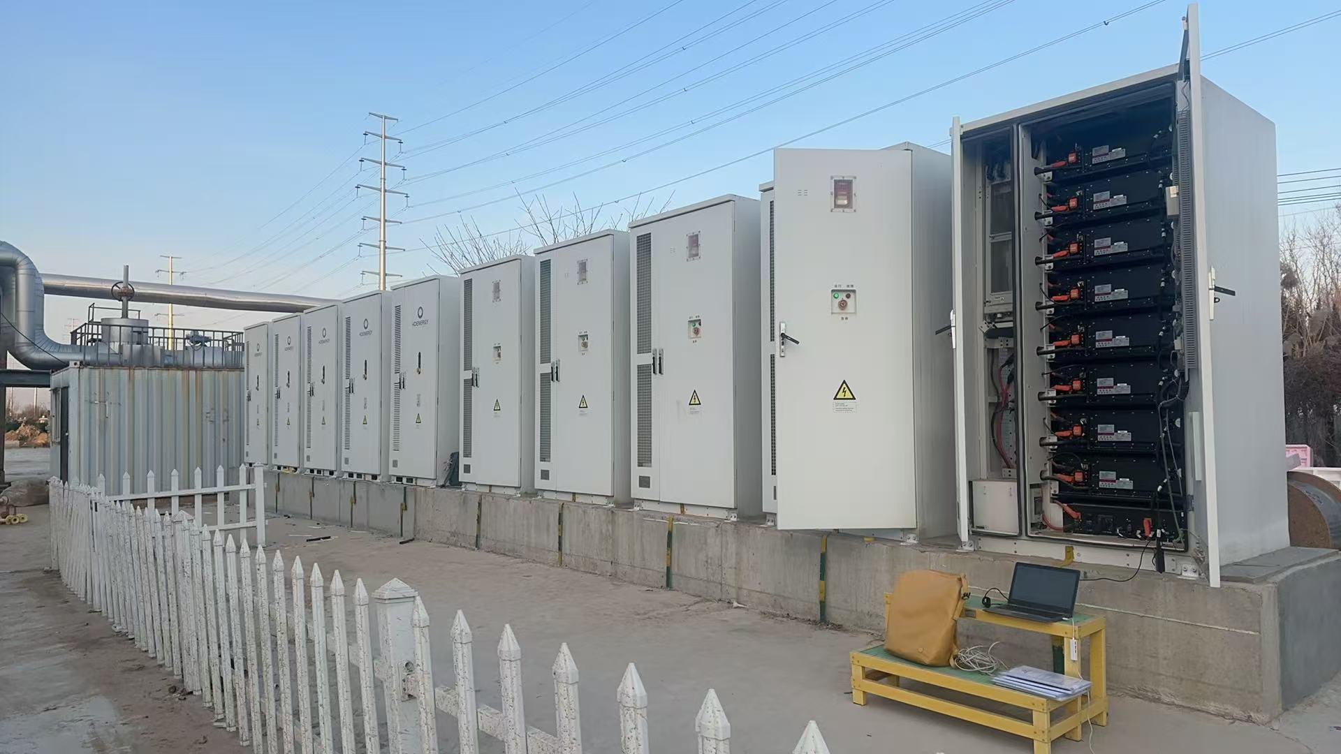
Revolutionary off-grid no-communication 12-unit parallel on-site
2. Grid-Connected Grid-Forming Support
2.1 Application Background
The grids in Finland and Brazil already mandate that grid-connected energy storage must have grid-forming functions. Turkey in Europe requires a frequency regulation response time of 100 ms, and Germany is also drafting grid-forming revenue standards.
PCS with grid-forming functions present more stable and flexible power source characteristics on the source-grid side. They use three core mechanisms—virtual damping, inertia response, and virtual impedance reshaping—to reduce system resonance risk, help the new power system achieve more stable voltage and frequency, and build a new power system revenue model.
2.2 Supported Product List
| Product Series | Power | Voltage Level | PCS Model | Product Model |
|---|---|---|---|---|
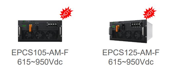
| Commercial & Industrial PCS IP20 | 125 kW | AC 400 V | EPCS125-AM / EPCS125-AM-F | D-Cube-A500/375/250, D-Cube-S125/261-EU |
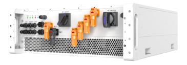
| 1500 V Platform IP66 | 215 kW | AC 690 V / 800 V | EPCS215-AM-HX | D-Cube-215/418 |
2.3 Application Solution
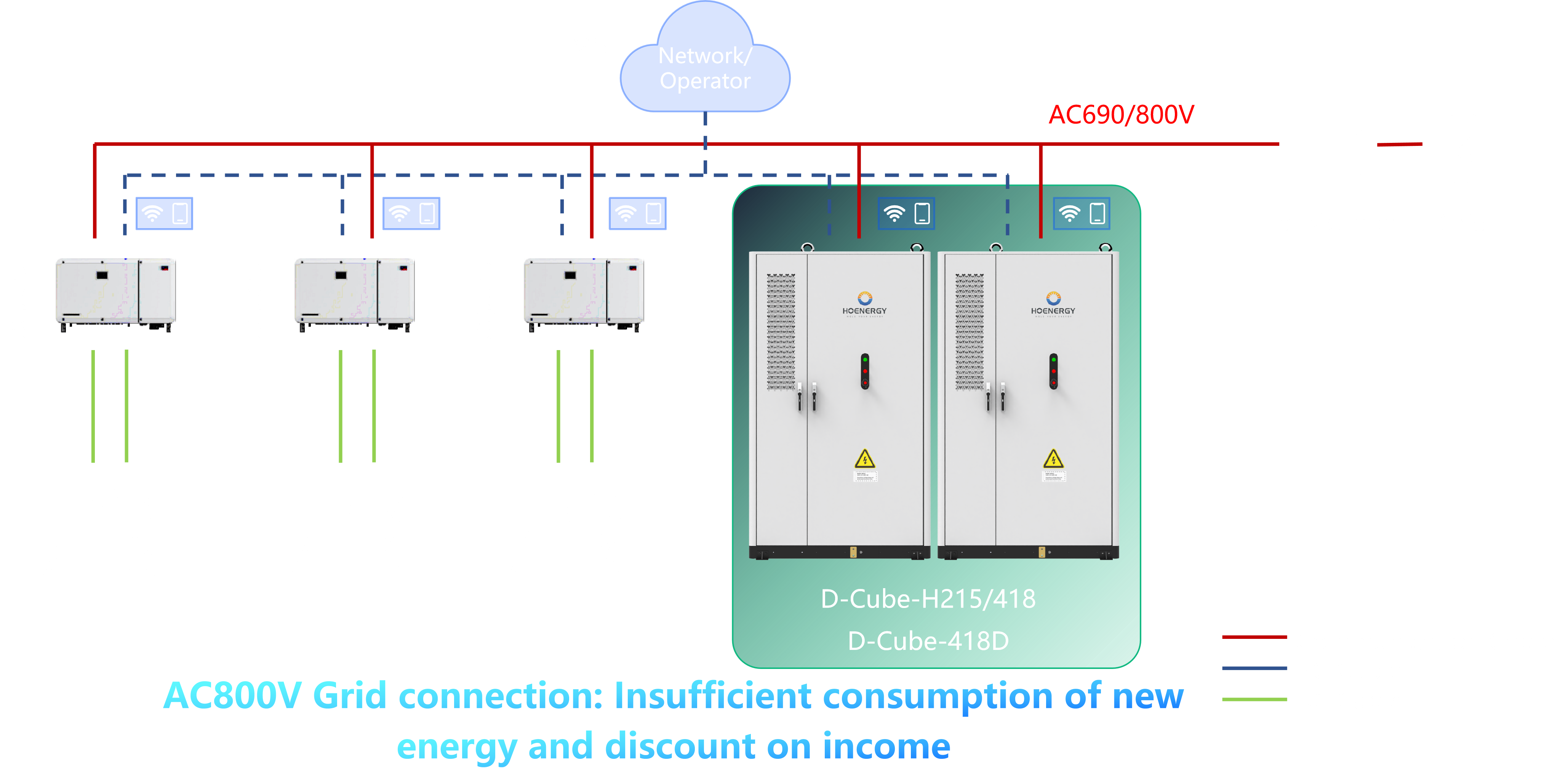
800V AC-Coupled PV-Storage Multi-Branch Grid-Forming Solution
Compliance
The 215 kW PCS module has obtained 400V / 690V / 800V CE + European EN50549 grid-connection certification.
String Multi-Branch Solution
Provides cluster-level SOC balancing. The string multi-branch grid-forming solution ensures that any single energy storage branch failure does not affect system operation, guaranteeing high system online rate and stability.
800V Grid-Forming AC PV-Storage Coupling Solution
Supports 800 V AC output, which can be directly AC-coupled with mainstream PV inverters. Combined with the VSG grid-forming algorithm, the three core mechanisms—virtual damping, inertia response, and virtual impedance reshaping—provide grid-forming functions and reduce system resonance risk. The PV-storage system requires only one transformer for grid connection.
Grid-Connected VSG Grid-Forming Function
The energy storage system supports the following through the grid-connected grid-forming function:
- Microsecond-level passive primary frequency and voltage regulation
- Harmonic suppression
- Active secondary frequency and voltage regulation
- Flexible inertia support function
In the event of a grid-side fault, it provides a maximum of 1.5 times rated power for 200 ms of grid-forming support, helping the grid operate stably and creating a new passive revenue model for grid-connected energy storage systems.
3. Seamless Switching with the Grid
3.1 Product Form
| Solution | Adapted Products |
|---|---|
| Solution 1, Solution 2 | Full coverage of En Jiu PCS modules |
| Solution 3 | Currently only supports 125 kW Europe-Australia dual-relay version PCS (with VG terminal + passive DO interface) |
3.2 Introduction to Grid-Forming Switching Solutions
3.2.1 Solution 1: STS Module Configuration (250 kW - 500 kW - 1 MW)
VSG combined with STS module switching (20 ms switching time — grid-connected VSG switching to off-grid VSG)
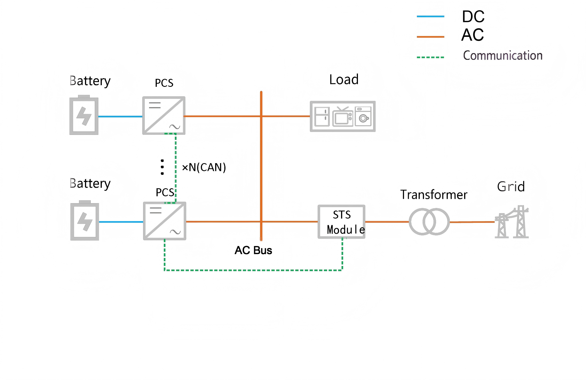 The entire process is driven by the STS module and PCS module for grid-connected/off-grid switching. CAN communication is required between the STS module and PCS. Compared with the traditional PQ/VF switching mode, VSG combined with the STS module uses weak communication, resulting in better communication stability, longer communication distance, and stronger anti-interference capability.
Load-carrying capacity during switching is superior to the traditional mode since it does not involve switching, with an increase of more than 30%.
3.2.2 Solution 2: Electric Operating Mechanism + Synchronizer Configuration (100 ms)
Application mode: For modules without VG terminals or when the grid-connection point switch is far away (communication from any one master unit is sufficient)
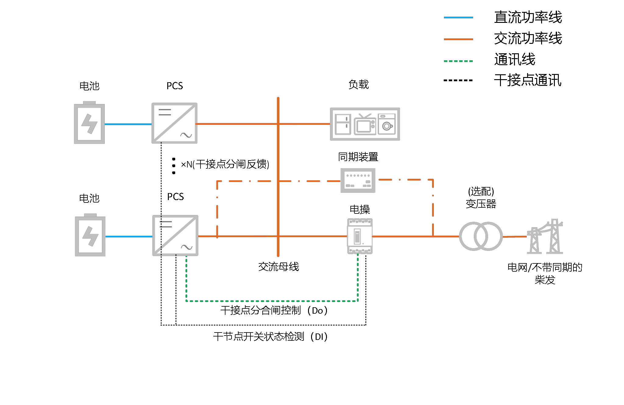 Grid-to-Off-Grid
Grid-to-off-grid: PCS operates in grid-connected VSG mode while performing active/passive islanding detection - Active islanding: When the grid loses power, PCS sends an opening command to the external switch and simultaneously switches to off-grid VSG mode - Passive islanding: When the grid loses power, PCS detects the external switch's open/close status through DI dry contacts and switches to off-grid VSG mode
Off-Grid-to-Grid
At this time, EMS adjusts the off-grid PCS voltage and frequency reference to align with the grid. The synchronizer detects synchronization and sends a dry contact signal for closing control. PCS reads the electric operating mechanism's open/close status and switches from off-grid to grid-connected VSG mode.
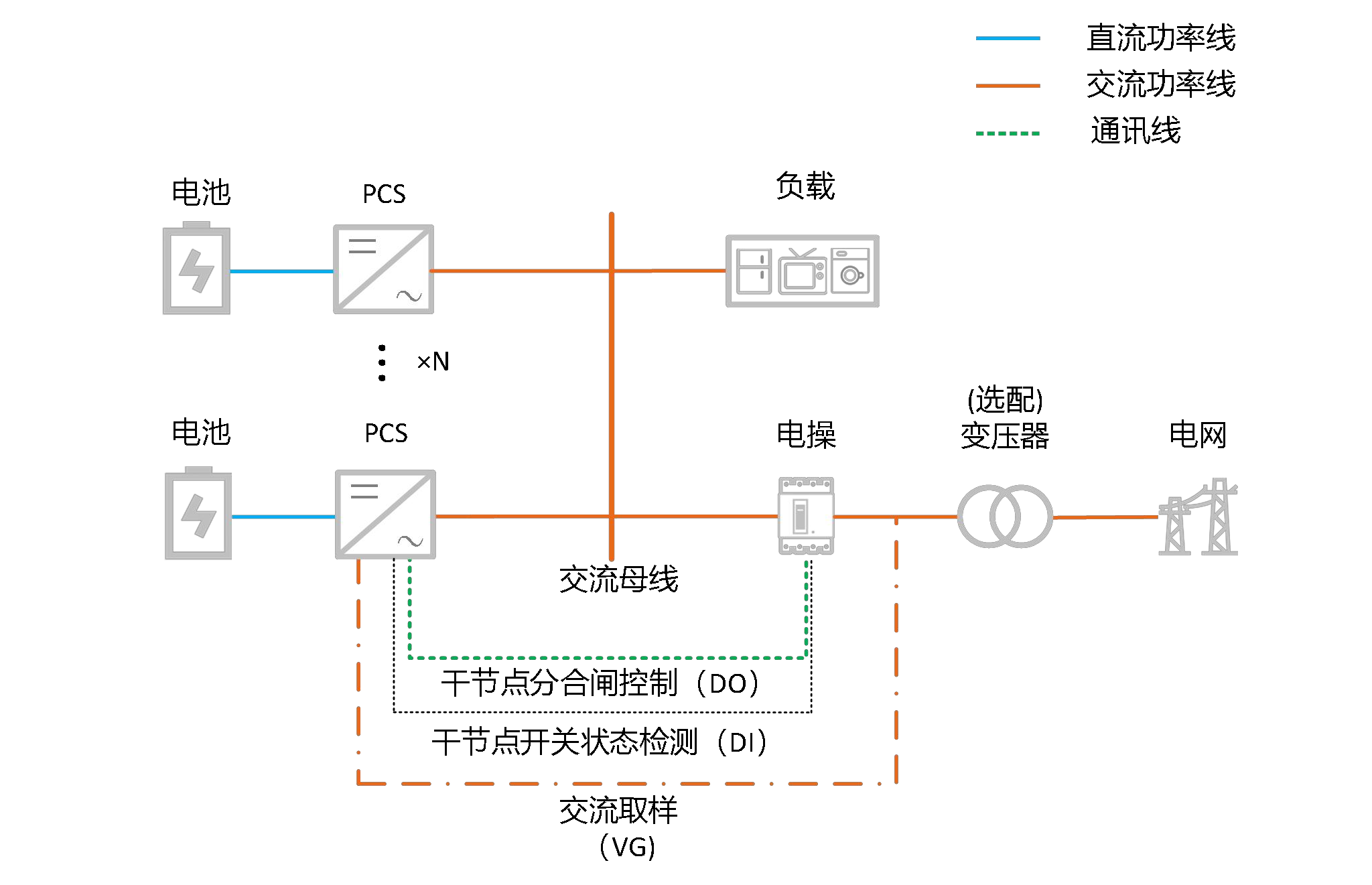
3.2.3 Solution 3: VG Sampling Synchronization Closing Scheme
- Electric operating mechanism switch + VG sampling configuration (100 ms) (communication from any one master unit is sufficient)
- Contactor switch + VG sampling configuration (20 ms) (communication from any one master unit is sufficient)
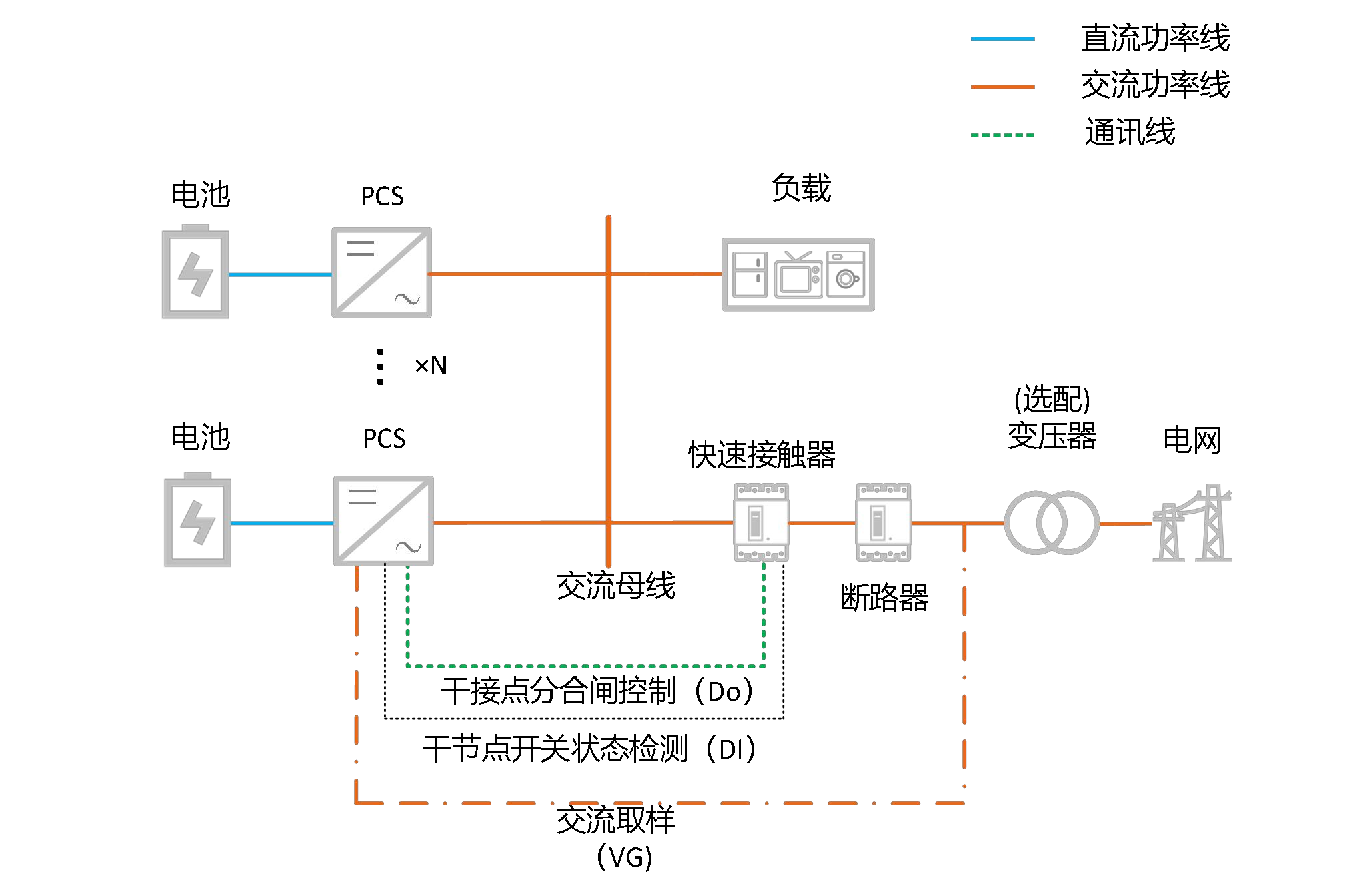
PCS operates in VSG mode. A set of DO dry contacts controls the open/close of the external switching switch, a set of DI dry contacts detects the open/close status of the external switch, and a set of voltage sampling monitors the voltage phase and amplitude on the grid side. Active islanding detection and passive islanding detection upon power loss are both completed by PCS. The synchronization for off-grid-to-grid switching is actively synchronized with the grid by PCS, which then sends a closing command to the electric operating mechanism.
Application Mode 1: Grid-side active opening protection switches to off-grid, shutdown closing switches to grid
- Grid-to-off-grid: PCS operates in grid-connected VSG mode, then the grid-side electric operating mechanism actively opens. PCS reads the electric operating mechanism's open/close status and switches to off-grid VSG mode.
- Off-grid-to-grid: PCS operates in off-grid VSG mode, shuts down first, then the electric operating mechanism closes. PCS switches to grid-connected VSG mode and starts up for grid connection.
Application Mode 2: Grid-side passive power loss switches to off-grid, automatic closing without shutdown for grid connection
- Grid-to-off-grid: PCS operates in grid-connected VSG mode while performing active/passive islanding detection
- Active islanding: When the grid loses power, PCS sends an opening command to the external switch and simultaneously switches to off-grid VSG mode
- Passive islanding: When the grid loses power, PCS detects the external switch's open/close status through DI dry contacts and switches to off-grid VSG mode
- Off-grid-to-grid: PCS operates in off-grid VSG mode. The synchronizer continuously monitors the grid-side status. After voltage recovery, it automatically synchronizes the grid-side phase and amplitude. Once synchronization is complete, it sends a closing command to the electric operating mechanism. PCS switches to grid-connected VSG mode based on DI dry contact status.
4. Diesel Generator and PV System Together Form a Microgrid to Bear Loads (Weak Grid Support)
4.1 Application Background and Pain Points
In remote areas with weak grids or in applications requiring backup power, diesel generators are typically used as a stable AC source for energy supply. However, diesel generators have expensive fuel costs, and when dealing with sudden load increases, the system transient characteristics are unstable, with large frequency and voltage drop ranges. Therefore, PV and energy storage are often added to microgrid systems to reduce diesel generator fuel consumption.
However, traditional PV-storage-diesel off-grid systems often have the following pain points.
Pain Point 1: Unstable Frequency and Voltage Characteristics of Diesel Generator Cause Frequent STS Switching or PLL Failure — Transient Fluctuations Trigger Cascading Failures
Small diesel generators (≤500 kW) commonly used in remote areas have slow governor response (typical response time 0.5-1 s) and low excitation system regulation accuracy. During sudden load increases (such as motor startup or welding machine operation):
- Frequency can instantaneously drop by 0.5-10 Hz
- Voltage drops by 15%-30%
STS switching trigger thresholds are typically set at frequency deviation ±0.5 Hz and voltage deviation ±10%. Diesel generator transient fluctuations easily trigger frequent switching. Meanwhile, the Phase-Locked Loop (PLL) needs to track the diesel generator's voltage phase. When voltage distortion exceeds 5% or frequency fluctuation rate exceeds 0.2 Hz/s, PLL fails, making it impossible to parallel PV-storage with the diesel generator.
Pain Point 2: Reverse Power Risk When Energy Storage in Grid-Connected Mode Shares Load with Diesel Generator — Source-Grid-Load Imbalance Causes Equipment Damage
The energy storage system in grid-connected mode uses a current source control strategy, with output power tracking command signals. The diesel generator, as a voltage source, maintains frequency and voltage stability through the governor and excitation system. The two have fundamentally different control logics. When PV output suddenly increases (such as when cloud shading disappears) or load suddenly drops (such as when large equipment shuts down), if the active power output from energy storage exceeds the real-time load demand, due to EMS response speed, excess electrical energy will flow back into the diesel generator. Since the diesel generator is a mechanical rotating device, reverse power will cause abnormal speed increase (5%-10% above rated speed), triggering governor protection actions and even causing fatigue damage to mechanical components such as the crankshaft and flywheel.
Pain Point 3: PV-Storage Capacity Limited by Diesel Generator Capacity and Characteristics Due to Resonance Risk — Clean Energy Utilization Severely Constrained
When the PV-storage system connects to the microgrid through inverters, its output impedance and the diesel generator's internal impedance (inductive impedance, which varies with load) and line impedance easily form series or parallel resonance at specific frequencies (typically 30-300 Hz). The smaller the diesel generator capacity, the larger the internal impedance variation range, and the higher the resonance risk. Meanwhile, synchronous and asynchronous diesel generators have significantly different internal impedance characteristics. Synchronous diesel generator excitation regulation exacerbates impedance fluctuations, further compressing the PV-storage capacity upper limit. The industry commonly adopts the empirical threshold of "PV-storage capacity ≤ 70% of diesel generator capacity," with some stringent scenarios requiring control to within 50%.
4.2 Product Advantage System Solution
4.2.1 STS-Free Diesel-Storage Cold Standby Switching Solution
When PCS operates in VSG (Virtual Synchronous Generator) mode, it has built-in phase-lock synchronization function. Therefore, when the diesel generator system establishes voltage and PCS connects to this system, PCS can automatically perform phase-lock synchronization according to the voltage source established by the diesel generator and connect to the system without additional equipment. Furthermore, through VSG's voltage and frequency control loop, coupled operation with the diesel generator is guaranteed, achieving joint grid-forming.
When the diesel generator connects to a PV-storage system that has already established a voltage source, due to different diesel generator types—some can only be used as single units, while others have built-in synchronization functions (synchronous generators)—different solutions are needed to adapt to different diesel generator types.
Application Scenario — Synchronous Generator Adaptation (No Auxiliary Switching Equipment Required)
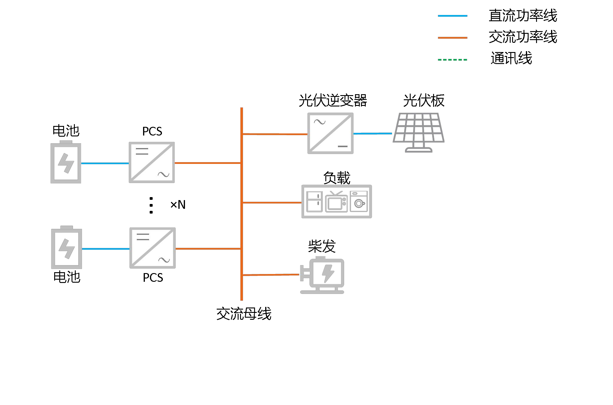 When the coupled generator in the system has built-in synchronization function, meaning the controller can synchronize with the external power source and then control the internal electric operating mechanism of the diesel generator to close. When coordinated with this type of synchronous generator and using VSG mode, the diesel generator system and energy storage system can freely switch seamlessly.
Application Scenario — Single-Unit Generator Adaptation
- Single-unit diesel generator switch-in: In off-grid state, the diesel generator does not start, PV-storage forms the grid. After SOC reaches the diesel generator startup threshold, the diesel generator starts and connects to the off-grid system through the synchronizer/VG sampling + electric operating mechanism. PCS reads the open/close status and switches to grid-connected VSG mode.
- Diesel generator switch-out: When SOC reaches the upper limit, EMS directly shuts down the diesel generator and sends an opening command. PCS reads the open/close status and switches to off-grid VSG mode.
Solution 1: Synchronizer + Electric Operating Mechanism
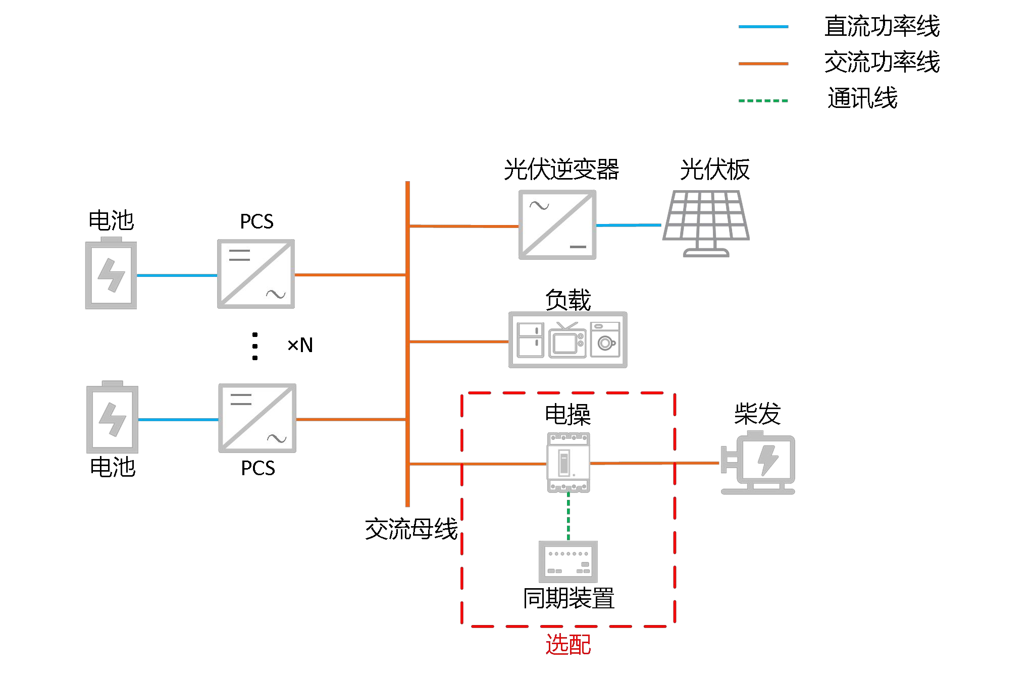 Through an external synchronizer + electric operating mechanism, phase synchronization is guaranteed when the diesel generator connects to the energy storage system before closing.
Solution 2: VG Sampling Terminal + Electric Operating Mechanism
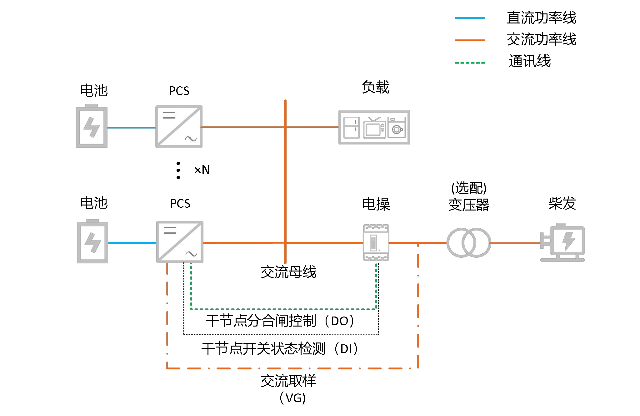 PCS uses the VG sampling terminal. After the diesel generator starts, PCS directly samples the diesel generator's voltage phase and frequency, actively performs phase synchronization with the diesel generator, and controls the electric operating mechanism to close once synchronization is confirmed. PCS then switches from off-grid VSG to grid-connected VSG mode by reading the switch status.
4.2.2 Diesel-Storage Hybrid VSG Application
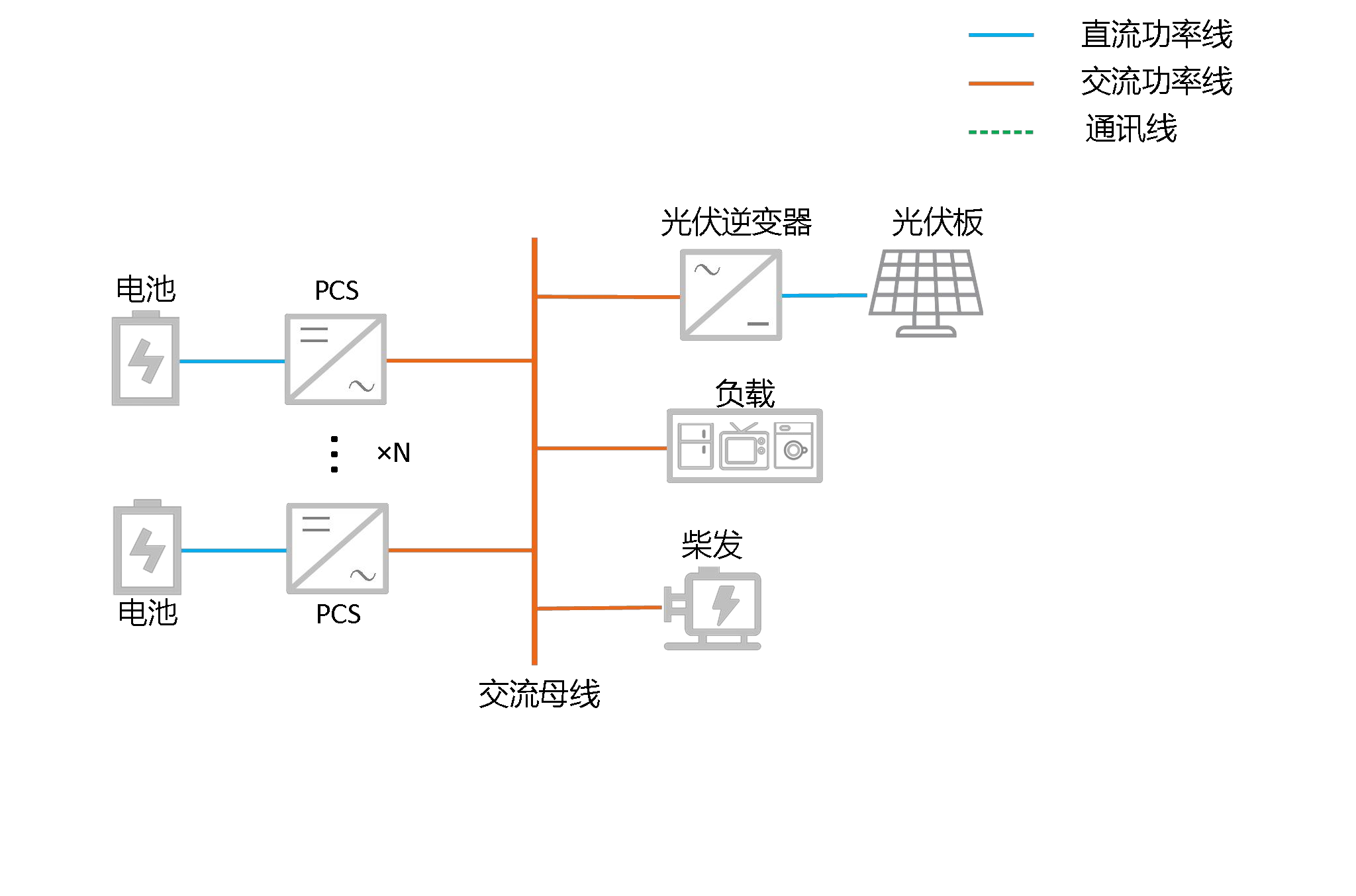 System Capacity Expansion Application
VSG has built-in primary frequency and voltage regulation support and inertia response, working with diesel generators to quickly support transient impact load changes with microsecond-level coordination. Depending on parameter configuration and diesel generator characteristics, the total system capacity can reach (diesel generator + energy storage) × (0.5 - 0.8). For example, with a 100 kW diesel generator and 100 kW energy storage, the system can suddenly pick up 100-160 kW under no-load conditions.
This application can also be used in diesel generator cold standby applications. If there are many inductive loads in the microgrid system, the capacity expansion application method can be used to bring the diesel generator into the system during load startup to temporarily expand capacity. After the inductive loads start, the diesel generator is shut down. This application allows the energy storage system configured capacity to be significantly reduced in microgrids with many inductive loads.
Load Power Distribution
EMS can provide active/reactive power commands to PCS through secondary frequency regulation, distributing loads to the diesel generator and energy storage system in steady state, such as maintaining the generator's optimal efficiency point.
Grid-Forming PV-Storage Capacity Expansion
The VSG grid-forming algorithm actively injects three core mechanisms—virtual damping, inertia response, and virtual impedance reshaping—into the system to reduce system resonance risk, enabling the energy storage system to jointly form the grid with the diesel generator. Compared with the traditional control mode where both PV-storage are current sources, the PV capacity calculation formula changes from
"PV-storage capacity ≤ 70% of diesel generator capacity"
to
"PV capacity = Energy storage capacity × 75% + Diesel generator capacity × 70%"
System Harmonic Suppression
When PCS in VSG mode collaborates with the diesel generator to form the grid, traditional current source control cannot optimize system harmonics and only adds 1-2% harmonic content on top of the original diesel generator system harmonics. VSG's voltage harmonic content is within 1-2%. Depending on capacity, energy storage can neutralize part of the lower harmonic content, offsetting diesel generator harmonic content of 3%-8%, resulting in overall system harmonic reduction.
5. Pure Off-Grid PCS Parallel Grid-Forming System
5.1 Application Background
In application scenarios in remote areas and islands, there is no large grid input, so pure off-grid PV-storage grid-forming is required. In large backup power application scenarios, multi-PCS parallel grid-forming is also required in off-grid state.
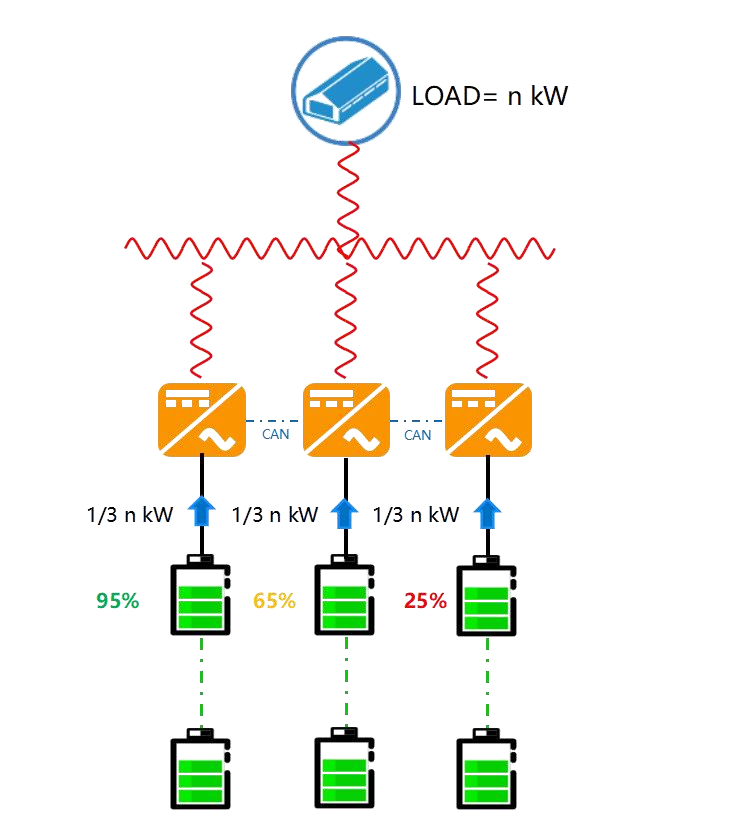
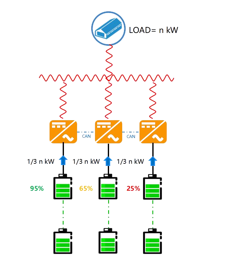
Traditional VF off-grid PCS parallel operation is limited by communication load rate, with total grid-forming capacity and communication distance constrained. Moreover, in off-grid state, active power control is not possible, and SOC balancing strategies cannot be implemented, affecting overall system stability and increasing maintenance costs.
5.2 Application Solution
5.2.1 Off-Grid Online SOC Balancing Function
Traditional VF Communication Architecture
VSG Parallel Architecture
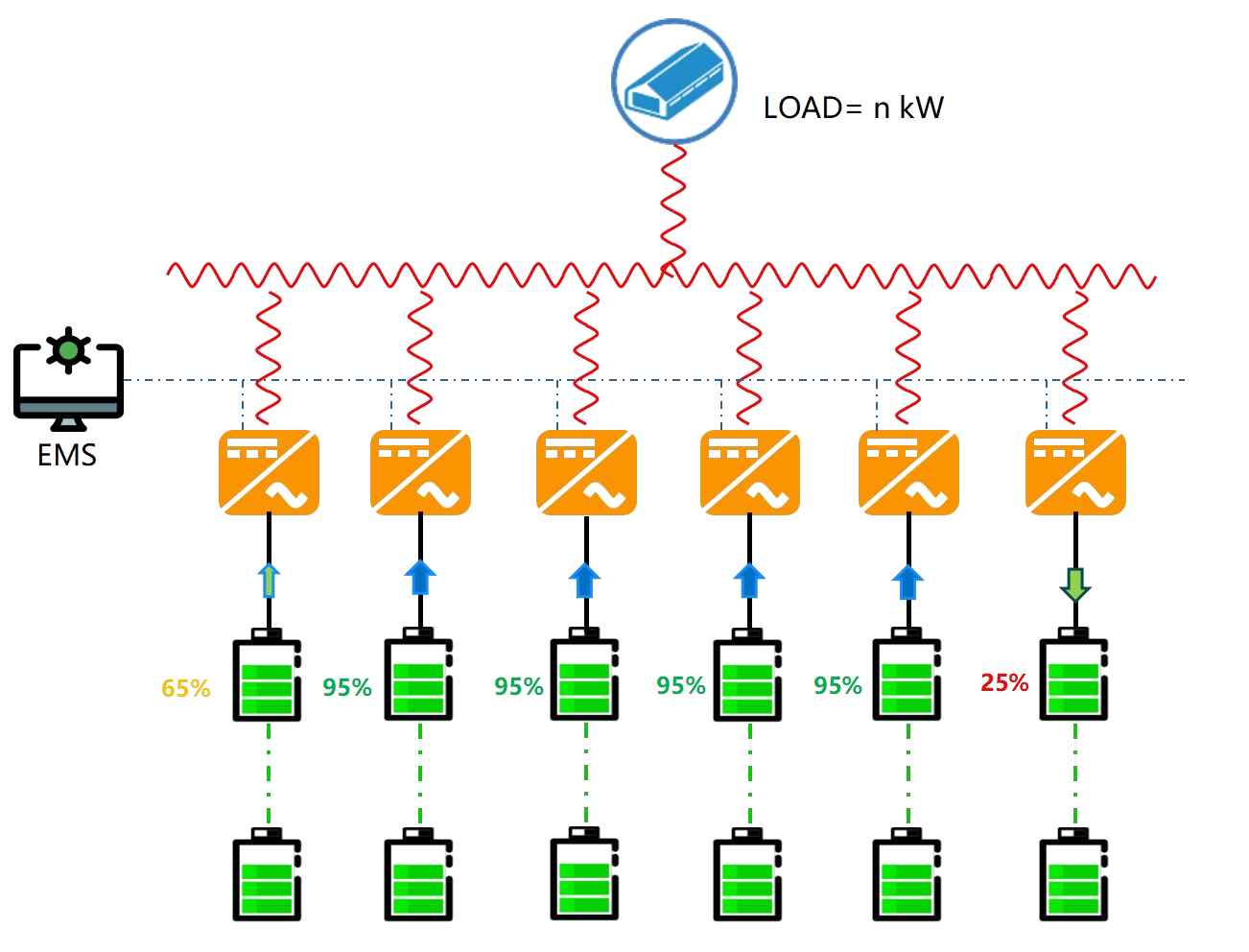
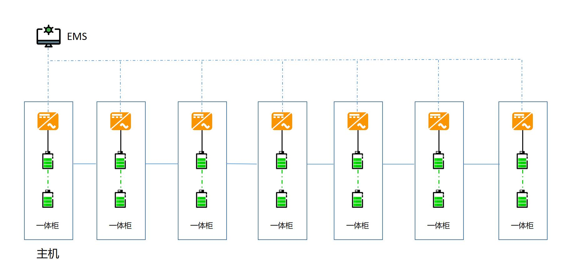
In VSG mode, parallel operation does not require communication line connections. Only EMS needs to separately regulate the secondary frequency and voltage regulation commands for each PCS to maintain system stability. Currently, up to 12 units can be paralleled. In off-grid state, charge/discharge commands for each PCS can be independently controlled through secondary frequency regulation commands.
5.2.2 Off-Grid Multi-Unit Parallel Grid-Forming Communication Solution
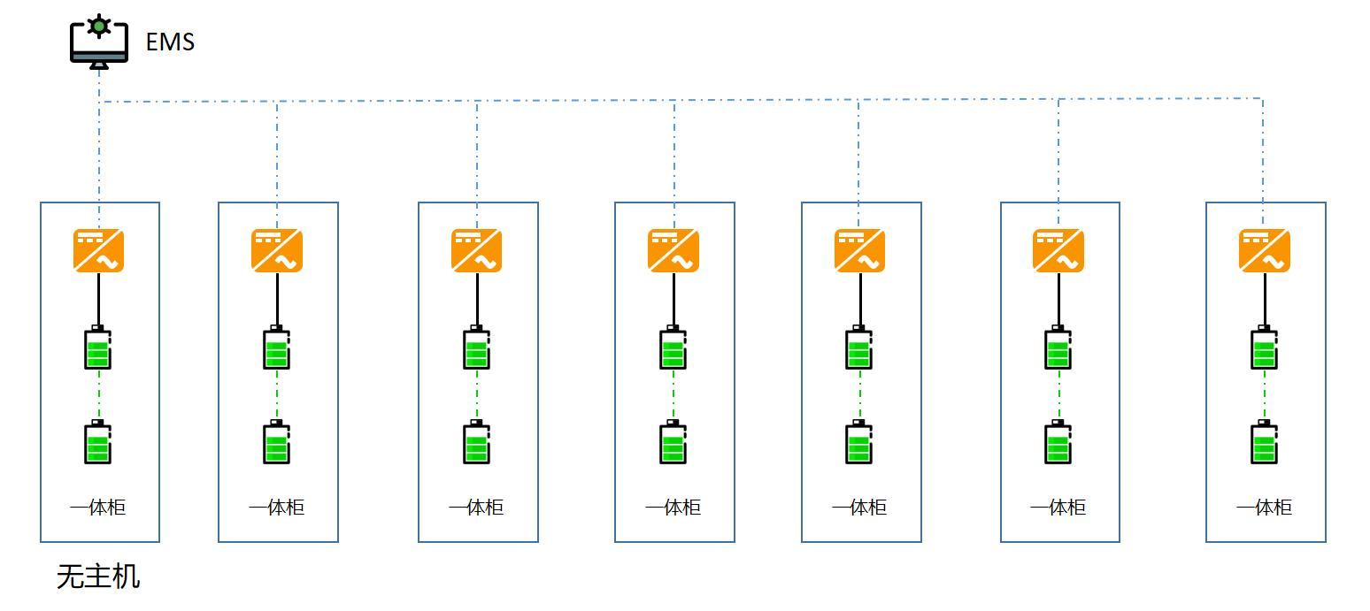
Multi-Cabinet No-Communication VSG Parallel
- Startup Method: EMS sends a startup command to any one unit through the communication line. That unit establishes voltage first, then sequentially sends startup commands to slave units, starting them one by one with an interval of 30 s.
- Control Method: EMS sends power commands to each PCS, which must follow Total PCS discharge power − Total PCS charge power = Load
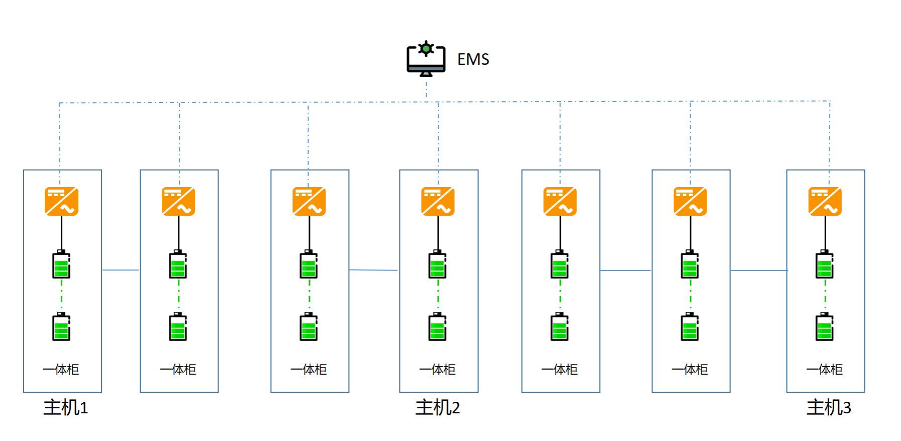
Multi-Cabinet Weak-Communication VSG Parallel
- Startup Method: EMS sends startup commands to all units through the communication line. The master and slave units then wait for command confirmation and automatically synchronize black start.
- Control Method: EMS sends total PCS power commands to the master unit. The master unit automatically and evenly distributes power to slave units.
- Weak Communication Description: Capable of synchronous one-key black start and EMS power command synchronization functions.
Multi-Cabinet Weak-Communication Long-Distance Grid-Forming No-Communication Parallel
- Control Method: EMS first sends a startup command through the communication line to the master unit with the largest capacity in the CAN group. After startup completion, it sequentially sends startup commands to master units of CAN communication groups with decreasing capacity, with a wait time of 30 s - 60 s between each.
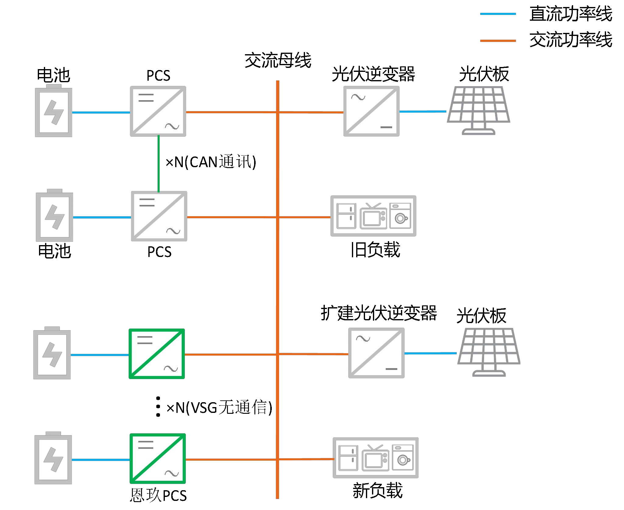
5.2.3 Off-Grid Project Capacity Expansion Application
For old pure off-grid projects, capacity expansion is often a pain point. Both adaptation to the old PCS communication architecture and whether communication load rate is sufficient must be considered.
In off-grid PCS, VSG no-communication grid-forming capacity expansion can be achieved, adapting to any brand of PCS without considering communication architecture, seamlessly expanding off-grid systems. All-in-one cabinets enable Place-and-Play, ready to use out of the box.
Appendix: Key Parameter Quick Reference Table
Three Core Mechanisms of VSG
| Mechanism | Simulated Object | Function |
|---|---|---|
| Virtual Inertia J | Rotor Kinetic Energy | Suppress RoCoF (Rate of Change of Frequency) |
| Virtual Damping D | Damping Winding/Friction | Negative feedback suppresses transient oscillation |
| Primary Frequency Regulation Kf | Governor Characteristic | P-f droop control, steady-state recovery |
PCS Product Array
| Series | Power | Voltage Level | Typical Application |
|---|---|---|---|
| IP20 | 105, 125 kW | AC 400 V | Commercial & Industrial |
| IP65 | 135 kW | AC 400/480 V | Commercial & Industrial |
| IP66 (1500V Platform) | 215 kW | AC 690/800 V | Large Commercial & Industrial / PV-Storage Coupling |
Switching Solution Comparison
| Solution | Configuration | Switching Time | Applicable Scenario |
|---|---|---|---|
| One | STS Module + PCS | 20 ms | Strong communication robustness |
| Two | Electric Operating Mechanism + Synchronizer | 100 ms | No VG terminal or remote switch |
| Three | VG Sampling + DI/DO (Electric Operating Mechanism) | 200 ms | 125 kW Europe-Australia dual-relay version |
| Three | VG Sampling + DI/DO (Contactor) | 20 ms | 125 kW Europe-Australia dual-relay version |
Key Benefits of Diesel-Storage Hybrid VSG
| Dimension | Traditional Solution | VSG Solution |
|---|---|---|
| STS Hardware Cost | 8-15% of system | No STS Required |
| Total System Capacity | Limited by diesel generator capacity | (Diesel generator + Energy storage) × (0.5-0.8) |
| PV Capacity Formula | ≤ 70% of diesel generator capacity | = Energy storage × 75% + Diesel generator × 70% |
| Voltage Harmonics | Diesel generator 3-8% | Energy storage can neutralize, overall reduction |
Off-Grid Parallel Solution Comparison
| Solution | Communication | Maximum Parallel Units | Distance | Startup Method |
|---|---|---|---|---|
| Traditional VF | CAN Required | 4-10 units | ≤50 m | Master-Slave Black Start |
| VSG No-Communication | Not Required | 12 units | Unlimited | EMS Sends to Units One by One |
| VSG Weak Communication | CAN Optional | Multiple units | ≤50 m | One-Key Black Start |
| VSG Weak Communication Long-Distance | Grouped CAN | Multiple units | Unlimited | Synchronized Within CAN Group |